Invacare CLTD Owners Manual
Invacare CLTD Manual
 |
View all Invacare CLTD manuals
Add to My Manuals
Save this manual to your list of manuals |
Invacare CLTD manual content summary:
- Invacare CLTD | Owners Manual - Page 1
's Operator and Maintenance Manual Compass™SPT™ Compass SPT Limited DEALER: This manual MUST be given to the user of the wheelchair. USER: BEFORE using this wheelchair, read this manual and save for future reference. For more information regarding Invacare products, parts, and services, please visit - Invacare CLTD | Owners Manual - Page 2
OWNER'S OPERATOR AND MAINTENANCE MANUAL, THE SERVICE MANUAL (IF APPLICABLE) AND THE SEATING SYSTEM'S MANUAL (IF APPLICABLE). IF YOU ARE UNABLE TO UNDERSTAND THE WARNINGS, CAUTIONS AND INSTRUCTIONS, CONTACT INVACARE TECHNICAL SUPPORT BEFORE ATTEMPTING TO SERVICE OR OPERATE THIS EQUIPMENT - OTHERWISE - Invacare CLTD | Owners Manual - Page 3
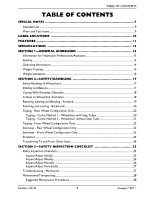
25 Safety Inspection Checklists...25 Inspect/Adjust Initially ...25 Inspect/Adjust Weekly...26 Inspect/Adjust Monthly...26 Inspect/Adjust Periodically...27 Troubleshooting - Mechanical ...27 Maintenance/Transporting...28 Suggested Maintenance Procedures 28 Part No 1122134 3 Compass™SPT™ - Invacare CLTD | Owners Manual - Page 4
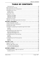
TABLE OF CONTENTS TABLE OF CONTENTS Transporting the Invacare Compass SPT 29 SECTION 4-FRONT RIGGINGS 30 Installing/Removing Swingaway Front Riggings 30 Installing...30 Removing ...30 Installing/Removing Lift-Off Footrest 31 Installing...31 Removing ...31 Adjusting Footrest Height ...31 Height - Invacare CLTD | Owners Manual - Page 5
TABLE OF CONTENTS TABLE OF CONTENTS Adjusting Armrest...40 Replacing Dual Point Arm Pad ...41 Replacing Dual Point Arm Clothing Guards 41 Installing/Removing T-Arms ...42 Installing T-Arms ...42 Removing T-Arms...42 Adjusting The T-Arms...43 Adjusting T-Arm Height ...43 Adjusting T-Arm Width ...44 - Invacare CLTD | Owners Manual - Page 6
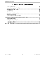
TABLE OF CONTENTS TABLE OF CONTENTS Replacing Caster/Fork...57 Replacing/Repairing Caster Tire/Tube 58 Installing/Removing Rear Wheels ...58 Quick-Release ...58 Permanent Axle...59 Adjusting the Quick-Release Axle ...59 Replacing Wheel Handrim...60 Replacing/Repairing Wheel Tire/Tube 60 SECTION 9- - Invacare CLTD | Owners Manual - Page 7
SPECIAL NOTES SPECIAL NOTES Signal words are used in this manual and apply to hazards or unsafe practices which could result in personal injury or property damage. Refer to the table below for definitions of the - Invacare CLTD | Owners Manual - Page 8
SPECIAL NOTES ƽ WARNING Use of non-Invacare accessories may result in serious injury or damage. Invacare products are specifically designed and manufactured for use in conjunction with Invacare accessories. Accessories designed by other manufacturers have not been tested by Invacare and are not - Invacare CLTD | Owners Manual - Page 9
item back that has an alleged defect in workmanship. See Warranty policy shipped with the product for specific warranty information. Refer to User Manual for proper preventative maintenance schedule and use of the product. This is just a general guideline and does not include items damaged due to - Invacare CLTD | Owners Manual - Page 10
axle bushing for a positive lock. Keep detent balls clean. REV.10/98 1026960 Before using this product, read and understand the User Manual. The user manual provides proper operation and safe practices. Documentation can be obtained at: • www.invacare.com • ph (440) 329-6000 • One Invacare Way - Invacare CLTD | Owners Manual - Page 11
FEATURES FEATURES Adjustable Angle/ Folding Back 12, 20, 22, 24-Inch Wheels Anti-Tippers Adjustable Arms (Optional) Adjustable Seat Depth Quick-Release Axles 6, 8-Inch Caster/ Fork Assembly Swingaway Footrest Part No 1122134 11 Compass™SPT™ - Invacare CLTD | Owners Manual - Page 12
SPECIFICATIONS SPECIFICATIONS INVACARE COMPASS SPT *OVERALL WIDTH: 27½ inches (seat width + 9½-inches) *OVERALL DEPTH: OVERALL HEIGHT: 33 to 39 inches 39½ inches (seat-to-floor + back cane height) ANTI-TIPPERS: Standard FOOTREST: Swing-Away Footrest Lift-off Footrest (Optional) Elevating - Invacare CLTD | Owners Manual - Page 13
SECTION 1-GENERAL GUIDELINES SECTION 1-GENERAL GUIDELINES Information for Healthcare Professionals/Assistants The Invacare Compass SPT wheelchair MUST be operated by a healthcare professional or assistant when in any tilt position. Stability The back height, seat depth, back angle, seating system - Invacare CLTD | Owners Manual - Page 14
stops on the gas cylinders to prevent the wheelchair from tipping onto the anti-tippers. Operating Information Unless otherwise noted, all service and adjustments should be performed while the wheelchair is unoccupied. To determine and establish your particular safety limits, practice bending - Invacare CLTD | Owners Manual - Page 15
damage to the wheelchair. DO NOT use the spreader bar for lifting or transporting the wheelchair. DO NOT use the spreader bar as a weight bearing support. DO NOT stand on the frame of the wheelchair. Part No 1122134 15 Compass™SPT™ - Invacare CLTD | Owners Manual - Page 16
holes. Ensure both anti-tippers are adjusted to the same mounting hole. Invacare strongly recommends that anti-tippers be used at all times. The manual wheelchair is intended for indoor and outdoor use on firm surfaces. When outdoors on wet, soft ground or on gravel surfaces, anti-tippers may - Invacare CLTD | Owners Manual - Page 17
the close attention of the wheelchair user as well as the assistant. This manual points out the most common procedures and techniques involved in the safe operation architectural barriers. Use this information only as a "basic" guide. The techniques that are discussed on the following pages have - Invacare CLTD | Owners Manual - Page 18
SECTION 2-SAFETY/HANDLING ƽ WARNING DO NOT attempt to reach objects if you have to move forward in the seat or pick them up from the floor by reaching down between your knees. The back height, seat depth, back angle, seating system, tilt angle, seat height, size/position of the wheels, size/ - Invacare CLTD | Owners Manual - Page 19
Also, be aware of detachable parts such as armrests or legrests. These must NEVER be used to move the wheelchair or as lifting supports, as they may be inadvertently released, resulting in possible injury to the user and/or assistant(s). When learning a new assistance technique, have an experienced - Invacare CLTD | Owners Manual - Page 20
SECTION 2-SAFETY/HANDLING Reaching and Leaning - Backwards ƽ WARNING DO NOT lean over the top of the back upholstery. This will change your center of gravity and may cause you to tip over. NOTE: For this procedure, refer to FIGURE 2.3. Position wheelchair as close as possible to the desired object. - Invacare CLTD | Owners Manual - Page 21
SECTION 2-SAFETY/HANDLING ƽ WARNING When lowering the casters of the wheelchair, DO NOT let the wheelchair drop the last few inches to the ground. This could result in injury to the occupant and/or damage to the wheelchair. Roll the wheelchair forward and slowly lower the front of the wheelchair in - Invacare CLTD | Owners Manual - Page 22
to moving. Invacare recommends using two assistants and making thorough preparations. Make sure to use ONLY secure, non-detachable parts for hand-held supports. Follow this procedure for moving the wheelchair up or down a curb when a ramp is NOT available: 1. Position the wheelchair as close to the - Invacare CLTD | Owners Manual - Page 23
moving. Invacare recommends using two assistants and making thorough preparations. Make sure to use ONLY secure, non-detachable parts for hand-held supports. Follow this procedure for moving the wheelchair between floors when an elevator is NOT available: 1. If necessary, swivel the anti-tippers so - Invacare CLTD | Owners Manual - Page 24
SECTION 2-SAFETY/HANDLING Escalators ƽ WARNING DO NOT use an escalator to move a wheelchair between floors. Serious bodily injury may occur. Transferring To and From Other Seats ƽ WARNING BEFORE attempting to transfer in or out of the wheelchair, every precaution should be taken to reduce the gap - Invacare CLTD | Owners Manual - Page 25
INSPECTION CHECKLIST SECTION 3-SAFETY INSPECTION CHECKLIST NOTE: Every six months take your wheelchair to a qualified technician for a thorough inspection and servicing. Regular cleaning will reveal loose or worn parts and enhance the smooth operation of your wheelchair. To operate properly and - Invacare CLTD | Owners Manual - Page 26
SECTION 3-SAFETY INSPECTION CHECKLIST ❑ Ensure all caster/wheel/fork/headtube fasteners are secure. ❑ Ensure wheel locks do not interfere with tires when rolling. ❑ Ensure wheel lock pivot points are free of wear and looseness. ❑ Ensure wheel locks are easy to engage. ❑ Inspect tires for flat spots - Invacare CLTD | Owners Manual - Page 27
Clean upholstery and armrests. ❑ Clean and wax all parts. ❑ Check that all labels are present and legible. Replace if necessary. Troubleshooting - Mechanical CHAIR VEERS LEFT/RIGHT SLUGGISH TURN/PERFORMANCE CASTERS FLUTTER SQUEAKS AND RATTLES LOOSENESS IN CHAIR SOLUTIONS X X If pneumatic tires - Invacare CLTD | Owners Manual - Page 28
SECTION 3-SAFETY INSPECTION CHECKLIST Maintenance/Transporting ƽ WARNING After any adjustments, repair or service and BEFORE use, make sure all attaching hardware is tightened securely - otherwise injury or damage may result. CAUTION DO NOT over tighten hardware attaching to - Invacare CLTD | Owners Manual - Page 29
SECTION 3-SAFETY INSPECTION CHECKLIST 9. Periodically check gas cylinders for oil leaks. If oil leak is detected, gas cylinder(s) should be replaced. 10. Replace any labels that are missing, worn or torn. Refer to Label Locations on page 10 for a listing of the labels and their locations. - Invacare CLTD | Owners Manual - Page 30
wheelchair. 5. If necessary, adjust the footrest height. Refer to Installing/Removing Swingaway Front Riggings on page 30 Hinge Pins Telescoping Front Rigging Support Removing 1. Pull the front rigging release lever and rotate the footrest outward. 2. Lift up on front rigging and remove from the - Invacare CLTD | Owners Manual - Page 31
up or down on its mounting tube until the desired footrest height is achieved. 3. Reassemble the hex screw and coved spacer through the footrest upper support and mounting tube (FIGURE 4.3). Part No 1122134 31 Compass™SPT™ - Invacare CLTD | Owners Manual - Page 32
Front Riggings on page 30. 6. Repeat STEPS 1-5 for the opposite side of the wheelchair, if necessary. Hex Screw Coved Spacer Footrest Footrest Upper Support Mounting Tube FIGURE 4.3 Adjusting Footrest Height 60°, 70° and 70° Taper 70° MFX, 90°, 70° LIFT and 90° LIFT Footrests NOTE: For this - Invacare CLTD | Owners Manual - Page 33
Reinstall the footrest(s) onto the wheelchair. Refer to Installing/Removing Swingaway Front Riggings on page 30. Locknut Coved Washer Footrest Support Coved Washer Hex Bolt Lower Footrest 8. Reinstall any accessory onto the footrest(s). FIGURE 4.5 Adjusting Footrest Height Model PHW93 and PH904A - Invacare CLTD | Owners Manual - Page 34
for opposite footplate, if desired. Flat Screws Footplate Half Clamp Adjustment Screw 90° Footrest Support DETAIL "A" - SIDE VIEW OF FOOTPLATE AND FOOTREST SUPPORT Footrest Support Footplate Hinge Footplate Locknuts FIGURE 4.7 Adjusting Adjustable Angle Flip-up Footplates Compass™SPT™ 34 - Invacare CLTD | Owners Manual - Page 35
SECTION 4-FRONT RIGGINGS Composite/Articulating Footplate Heel Loop Replacement NOTE: For this procedure, refer to FIGURE 4.8. Disassembly Composite. 1. Remove the hex screw and coved spacer that secure the lower footrest assembly to the swing away footrest assembly. 2. Remove the lower footrest - Invacare CLTD | Owners Manual - Page 36
one of the following: • Raising: Lift legrest assembly up to desired height. • Lowering: Lift elevating legrest assembly up with one hand. While supporting the elevating legrest assembly (and user's leg), pull release lever up with other hand and lower legrest assembly to desired height. Release - Invacare CLTD | Owners Manual - Page 37
SECTION 4-FRONT RIGGINGS Adjusting Footplate Height and Calfpad Height/Depth NOTE: For this procedure, refer to FIGURE 4.11. Adjusting the Footplate Height 1. Loosen locknut and washer securing the slide tube to the elevating legrest. 2. Reposition footplate to desired height securely tighten - Invacare CLTD | Owners Manual - Page 38
, refer to FIGURE 4.13. 1. Remove the hex screw and washer that secure the existing sector block to the front rigging support tube. 2. Position the new sector block on the front rigging support tube. Make sure the locking pin is facing up. 3. Secure the new sector block to the front rigging - Invacare CLTD | Owners Manual - Page 39
SECTION 4-FRONT RIGGINGS Installing Impact Guards/Calf Strap/H-Calf Strap NOTE: For this procedure, refer to FIGURE 4.14. NOTE: Impact guards are standard equipment on Model ST footrests. No assembly is required. 1. Remove impact guard/calf strap from packaged container. 2. Secure the impact guards - Invacare CLTD | Owners Manual - Page 40
SECTION 5-ARMS SECTION 5-ARMS ƽ WARNING After any adjustments, repair or service and before use, make sure all attachment hardware is tightened securely - otherwise, injury or damage may result. DO NOT attempt to lift or tilt a wheelchair - Invacare CLTD | Owners Manual - Page 41
SECTION 5-ARMS 3. Lock the armrest assembly by pressing the release lever into the down (vertical) position as shown in Detail "A". 4. Pull up on the armrest assembly to ensure the armrest is locked in place. 5. Repeat STEPS 1-4 for opposite side of wheelchair, if necessary. DETAIL "A" Locked - - Invacare CLTD | Owners Manual - Page 42
SECTION 5-ARMS 2. Replace the existing clothing guard with the new clothing guard and securely tighten with the existing hardware. 3. Repeat STEPS 1-2 for the opposite side if necessary. Installing/Removing T-Arms NOTE: For this procedure, refer to FIGURE 5.3. Installing T-Arms 1. Position the T- - Invacare CLTD | Owners Manual - Page 43
Adjusting The T-Arms SECTION 5-ARMS Adjusting T-Arm Height NOTE: For this procedure, refer to FIGURE 5.4. 1. Unlock the T-Arm by flipping the T-Arm release lever towards the inside of the wheelchair. NOTE: If necessary, pull the T-Arm release lever out and rotate 180° so it can be flipped towards - Invacare CLTD | Owners Manual - Page 44
SECTION 5-ARMS Adjusting T-Arm Width NOTE: For this procedure, refer to FIGURE 5.5. 1. Remove the two mounting screws that secure the arm pad to the arm tube. 2. Turn the arm pad around and reposition the arm pad on the arm tube. 3. Re-secure the arm pad to the arm tube with the two mounting screws - Invacare CLTD | Owners Manual - Page 45
SECTION 5-ARMS Adjusting T-Arm Sockets NOTE: For this procedure, refer to FIGURE 5.7. NOTE: Perform this procedure if the T-Arm is too loose in the socket or does not easily slide UP and DOWN in the socket. 1. Remove the rear wheels from the wheelchair, if necessary. Refer to Installing/Removing - Invacare CLTD | Owners Manual - Page 46
SECTION 5-ARMS Adjusting T-Arm Transfer Assists And/or Side Guards NOTE: For this procedure, refer to FIGURE 5.8. 1. Remove the T-Arm from the wheelchair. Refer to Installing/Removing T-Arms on page 42. 2. Remove the two socket screws that secure the side guard to the bottom clamp. NOTE: Adjusting - Invacare CLTD | Owners Manual - Page 47
SECTION 6-BACK/SEAT SECTION 6-BACK/SEAT ƽ WARNING After adjustments and before use make sure all attaching hardware is securely tightened. Folding/Unfolding Back Assembly NOTE: For this procedure, refer to FIGURE 6.1. NOTE: When folding or unfolding the back, make sure the back release cord does not - Invacare CLTD | Owners Manual - Page 48
for use with Invacare products. 1. Ensure that the seating system is compatible with this wheelchair. 2. Refer to the seating system Owner's Manual for installation and removal. Installing Stroller Handle NOTE: For this procedure, refer to FIGURE 6.2. 1. Remove the plug buttons from both back - Invacare CLTD | Owners Manual - Page 49
SECTION 6-BACK/SEAT Installing/Removing/Adjusting the Adjustable Angle Stroller Handles NOTE: For this procedure, refer to FIGURE 6.3. Installing 1. Remove plug buttons from both back canes. 2. Slide the adjustable height stroller handle into the back canes. 3. Align the mounting holes of the - Invacare CLTD | Owners Manual - Page 50
SECTION 6-BACK/SEAT Adjusting/Replacing the Back Release Cord ƽ WARNING The back MUST be locked securely in place before using the wheelchair. NOTE: For this procedure, refer to FIGURE 6.4. NOTE: The back release cord may be adjusted to a tight or loose fit to meet the need of the user. Adjusting - Invacare CLTD | Owners Manual - Page 51
SECTION 6-BACK/SEAT Installing/Replacing Seat Positioning Straps NOTE: For this procedure, refer to FIGURE 6.5. Installing 1. Remove the hex screw and locknut that secures the back cane to the back plate. 2. Position the seat positioning strap against the back plate. 3. Install the hex screw - Invacare CLTD | Owners Manual - Page 52
SECTION 6-BACK/SEAT Installing/Replacing Chest Positioning Straps NOTE: For this procedure, refer to FIGURE 6.6. Installing 1. Position the chest positioning strap to one of the holes on the back cane. NOTE: The standard recommended position for the chest positioning strap is in the top hole of the - Invacare CLTD | Owners Manual - Page 53
SECTION 7-TILT SECTION 7-TILT ƽ WARNING After ANY adjustments, repair or service and BEFORE use, make sure all attaching hardware is tightened securely - otherwise injury or damage may occur. Engaging Tilt-In-Space ƽ WARNING Both gas cylinders - Invacare CLTD | Owners Manual - Page 54
SECTION 7-TILT 7. When the seat reaches the desired angle, slow let go of the trigger release levers. 8. To lower the seat parallel with the floor, reverse the above sections. Trigger Release Lever Back Cane FIGURE 7.1 Engaging Tilt-In-Space Adjusting Trigger Release Cables NOTE: For this - Invacare CLTD | Owners Manual - Page 55
SECTION 7-TILT • To Tighten - Turn the cable adjusting nut clockwise. DO NOT overtighten the cable adjusting nut (FIGURE 7.2). • To Loosen - Turn the cable adjusting nut counterclockwise (FIGURE 7.2). C. While holding the cable adjusting nut in place, tighten the cable locking nut against the cable - Invacare CLTD | Owners Manual - Page 56
SECTION 7-TILT Actuator Centered Opening Actuator Housing Cable Locking Nut Cable Adjusting Nut Trigger Release Lever DETAIL "A" Actuator Too Low Opening Actuator Housing Actuator Too High Opening Actuator Housing FIGURE 7.2 Adjusting Trigger Release Cables Compass™SPT™ 56 Part No 1122134 - Invacare CLTD | Owners Manual - Page 57
SECTION 8-WHEELS SECTION 8-WHEELS ƽ WARNING After adjustments and before use make sure all attaching hardware is securely tightened. Installing/Replacing Six or Eight-inch Caster/Fork NOTE: For this procedure, refer to FIGURE 8.1. Installing Caster/Fork 1. Remove the casters from the accessory - Invacare CLTD | Owners Manual - Page 58
SECTION 8-WHEELS Replacing/Repairing Caster Tire/Tube ƽ WARNING Replacement of caster tire or tube MUST be performed by a qualified technician. CAUTION As with any vehicle, the wheels and tires should be checked periodically for cracks and wear, and should be replaced. Installing/Removing Rear - Invacare CLTD | Owners Manual - Page 59
SECTION 8-WHEELS Permanent Axle NOTE: For this procedure, refer to FIGURE 8.3. NOTE: To remove rear wheels, reverse this procedure. 1. Remove the permanent axles from the packaged container. Wheelchair Frame 2. Install permanent axle through the rear wheel and axle plate. 3. Securely tighten - Invacare CLTD | Owners Manual - Page 60
SECTION 8-WHEELS Replacing Wheel Handrim NOTE: For this procedure, refer to FIGURE 8.5. 1. Remove the wheel from the wheelchair. Refer to Installing/Removing Rear Wheels on page 58. 2. Remove the button screws that secure the existing handrim to the wheel. 3. Remove the existing handrim. 4. Install - Invacare CLTD | Owners Manual - Page 61
SECTION 9-WHEEL LOCKS AND ANTI-TIPPERS SECTION 9-WHEEL LOCKS AND ANTI-TIPPERS ƽ WARNING After adjustments and before use make sure all attaching hardware is securely tightened. Wheel Lock Adjustment NOTE: For this procedure, refer to FIGURE 9.1. NOTE: Before adjusting the wheel lock assemblies, - Invacare CLTD | Owners Manual - Page 62
holes. Ensure both anti-tippers are adjusted to the same mounting hole. Invacare strongly recommends that anti-tippers be used at all times. The manual wheelchair is intended for indoor and outdoor use on firm surfaces. When outdoors on wet, soft ground or on gravel surfaces, anti-tippers may - Invacare CLTD | Owners Manual - Page 63
SECTION 9-WHEEL LOCKS AND ANTI-TIPPERS Adjusting Anti-Tippers NOTE: A 1½ to 2-inch clearance between the bottom of the anti-tipper wheels and the floor MUST be maintained at all times. 1. Press the release button in and adjust the anti-tipper until the spring button protrudes from the other - Invacare CLTD | Owners Manual - Page 64
SECTION 9-WHEEL LOCKS AND ANTI-TIPPERS NOTES Compass™SPT™ 64 Part No 1122134 - Invacare CLTD | Owners Manual - Page 65
SECTION 9-WHEEL LOCKS AND ANTI-TIPPERS NOTES Part No 1122134 65 Compass™SPT™ - Invacare CLTD | Owners Manual - Page 66
SECTION 9-WHEEL LOCKS AND ANTI-TIPPERS NOTES Compass™SPT™ 66 Part No 1122134 - Invacare CLTD | Owners Manual - Page 67
shall be limited to such repair and/or replacement. For warranty service, please contact the dealer from whom you purchased your Invacare product. THE WARRANTY SHALL NOT APPLY TO PROBLEMS ARISING FROM NORMAL WEAR OR FAILURE TO ADHERE TO THESE INSTRUCTIONS. THE FOREGOING EXPRESS WARRANTY IS EXCLUSIVE - Invacare CLTD | Owners Manual - Page 68
Invacare Corporation USA One Invacare Way Elyria, Ohio USA 44036-2125 800-333-6900 www.invacare.com Canada 570 Matheson Blvd E Unit 8 Mississauga Ontario L4Z 4G4 Canada 800-668-5324 Making Life's Experiences Possible™ © 2015 Invacare Corporation. All rights reserved. Republication, duplication or
-
 1
1 -
 2
2 -
 3
3 -
 4
4 -
 5
5 -
 6
6 -
 7
7 -
8
-
9
-
10
-
11
-
12
-
13
-
14
-
15
-
16
-
17
-
18
-
19
-
20
-
21
-
22
-
23
-
24
-
25
-
26
-
27
-
28
-
29
-
30
-
31
-
32
-
33
-
34
-
35
-
36
-
37
-
38
-
39
-
40
-
41
-
42
-
43
-
44
-
45
-
46
-
47
-
48
-
49
-
50
-
51
-
52
-
53
-
54
-
55
-
56
-
57
-
58
-
59
-
60
-
61
-
62
-
63
-
64
-
65
-
66
-
67
-
68
 |
 |
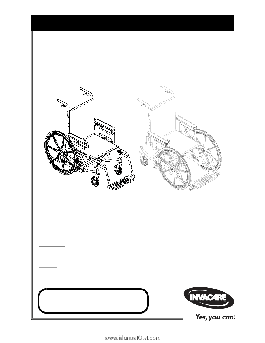
Owner’s Operator and Maintenance Manual
DEALER:
This manual MUST be given to
the user of the wheelchair.
USER:
BEFORE using this wheelchair, read
this manual and save for future reference.
For more information regarding
Invacare products,
parts, and services,
please visit www.invacare.com
Compass™SPT™
Compass SPT Limited