Invacare CLTD Owners Manual - Page 33
Installing Adjustable Angle Flip-up Footplate Hinge,
 |
View all Invacare CLTD manuals
Add to My Manuals
Save this manual to your list of manuals |
Page 33 highlights
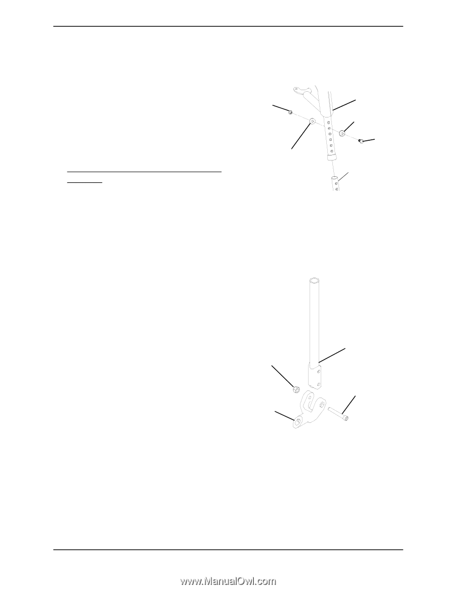
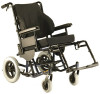
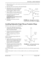
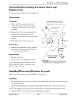
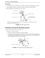
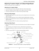
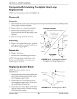
SECTION 4-FRONT RIGGINGS 3. Remove the hex bolt, coved washers and locknut that secure the lower footrest to the footrest support. 4. Reposition the lower footrest to the desired height. 5. Reinstall hex bolt, coved washers and locknut that secure lower footrest to footrest support. Tighten securely. 6. Repeat STEPS 1-5 for the opposite side of the wheelchair footrest, if necessary. 7. Reinstall the footrest(s) onto the wheelchair. Refer to Installing/Removing Swingaway Front Riggings on page 30. Locknut Coved Washer Footrest Support Coved Washer Hex Bolt Lower Footrest 8. Reinstall any accessory onto the footrest(s). FIGURE 4.5 Adjusting Footrest Height Model PHW93 and PH904A Front Riggings Installing Adjustable Angle Flip-up Footplate Hinge NOTE: For this procedure, refer to FIGURE 4.6. 1. Position the adjustable angle flip-up \ footplate hinge on the footrest support tube at the desired height. 2. Position the hardware on the footrest support as shown in FIGURE 4.6. 3. Flip the footplate hinge to the UP position. NOTE: The footplate hinge will fall to the DOWN position. 4. Tighten the socket screw and locknut that secure the footplate hinge to the footrest support until the footplate hinge remains in the up position. Locknut Footplate Hinge Footrest Support Tube Socket Screw 5. Check the up and down motion of the footplate hinge to make sure the user of the wheelchair can operate the footplates easily. FIGURE 4.6 Installing Adjustable Angle Flip-up Footplate Hinge NOTE: If the footplate's motion is too tight, loosen the socket screw and locknut approximately ¼-turn. NOTE: If the footplate's motion is too loose, tighten socket screw and locknut approximately ¼-turn. Part No 1122134 33 Compass™SPT™
-
 1
1 -
2
-
3
-
4
-
5
-
6
-
7
-
8
-
9
-
10
-
11
-
12
-
13
-
14
-
15
-
16
-
17
-
18
-
19
-
20
-
21
-
22
-
23
-
24
-
25
-
26
-
27
-
 28
28 -
 29
29 -
 30
30 -
 31
31 -
 32
32 -
 33
33 -
 34
34 -
 35
35 -
 36
36 -
 37
37 -
 38
38 -
39
-
40
-
41
-
42
-
43
-
44
-
45
-
46
-
47
-
48
-
49
-
50
-
51
-
52
-
53
-
54
-
55
-
56
-
57
-
58
-
59
-
60
-
61
-
62
-
63
-
64
-
65
-
66
-
67
-
68
 |
 |