Invacare CLTD Owners Manual - Page 32
° MFX, 90°, 70° LIFT and 90° LIFT Footrests, Model PHW93 and PH904A Front Riggings
 |
View all Invacare CLTD manuals
Add to My Manuals
Save this manual to your list of manuals |
Page 32 highlights
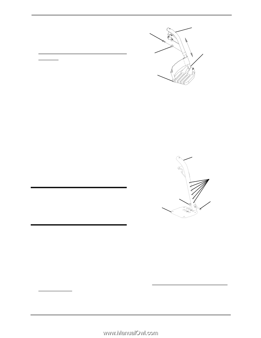
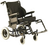
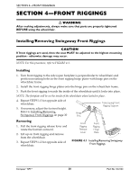
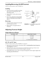
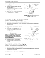
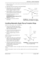
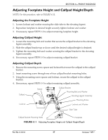
SECTION 4-FRONT RIGGINGS 4. Securely tighten the hex screw and coved spacer. 5. Install the footrest assembly onto the wheelchair. Refer to Installing/Removing Swingaway Front Riggings on page 30. 6. Repeat STEPS 1-5 for the opposite side of the wheelchair, if necessary. Hex Screw Coved Spacer Footrest Footrest Upper Support Mounting Tube FIGURE 4.3 Adjusting Footrest Height 60°, 70° and 70° Taper 70° MFX, 90°, 70° LIFT and 90° LIFT Footrests NOTE: For this procedure, refer to FIGURE 4.4. 1. Remove any accessories that are attached to the footrests. 2. Remove the socket bolt, coved washer and locknut that secure the footplate to the footrest support. 3. Reposition the footplate to the desired height. 4. Reinstall the socket bolt through the mounting holes of the footplate and footrest support. Footrest Support Height Adjustment Holes ƽ WARNING DO NOT overtighten socket bolt and locknut. Footrest MUST be able to rotate upward from the horizontal to the vertical position. 5. Secure the footplate to the footrest support with the coved washer and locknut. Locknut Footplate Socket Bolt FIGURE 4.4 Adjusting Footrest Height 70° MFX, 90°, 70° LIFT and 90° LIFT Footrests Model PHW93 and PH904A Front Riggings NOTE: For this procedure, refer to FIGURE 4.5 on page 33. 1. Remove any accessory from the footrest(s). 2. Remove the footrest from the wheelchair. Refer to Installing/Removing Swingaway Front Riggings on page 30. NOTE: Lay footrest on a flat surface to simplify procedure. Compass™SPT™ 32 Part No 1122134
-
 1
1 -
2
-
3
-
4
-
5
-
6
-
7
-
8
-
9
-
10
-
11
-
12
-
13
-
14
-
15
-
16
-
17
-
18
-
19
-
20
-
21
-
22
-
23
-
24
-
25
-
26
-
 27
27 -
 28
28 -
 29
29 -
 30
30 -
 31
31 -
 32
32 -
 33
33 -
 34
34 -
 35
35 -
 36
36 -
 37
37 -
38
-
39
-
40
-
41
-
42
-
43
-
44
-
45
-
46
-
47
-
48
-
49
-
50
-
51
-
52
-
53
-
54
-
55
-
56
-
57
-
58
-
59
-
60
-
61
-
62
-
63
-
64
-
65
-
66
-
67
-
68
 |
 |