Invacare TDXSP Owners Manual 4 - Page 35
Adjusting Armrests, Angle, Height, DETAIL B - HEIGHT, DETAIL A - ANGLE
 |
View all Invacare TDXSP manuals
Add to My Manuals
Save this manual to your list of manuals |
Page 35 highlights
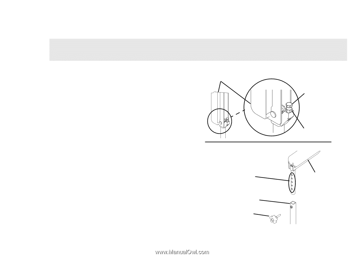
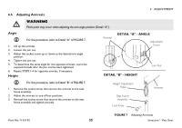
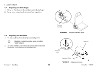
6.6 Adjusting Armrests 6 ADJUSTMENT ƽ WARNING Pinch point may occur when adjusting the arm angle position (Detail "A"). Angle For this procedure, refer to Detail "A" of FIGURE 7. 1. Lift up the armrest. 2. Loosen the jam nut. 3. Adjust the socket screw up or down to the desired arm angle position. 4. Tighten the jam nut. 5. To determine the same angle for the opposite armrest, count the exposed threads after the jam nut has been tightened. 6. Repeat STEPS 1-4 for opposite armrest, if necessary. Height For this procedure, refer to Detail "B" of FIGURE 7. 1. Remove the socket screw that secures the armrest to the seat frame assembly. 2. Adjust the armrest to one of four positions. 3. Reinstall the socket screw that secures the armrest to the seat frame assembly and tighten securely. Armrest DETAIL "A" - ANGLE Adjustment Screw DETAIL "B" - HEIGHT Height Adjustment Holes Seat Frame Assembly Lock Knob Jam Nut Armrest Part No 1143195 FIGURE 7 Adjusting Armrests 35 Invacare® Van Seat
-
 1
1 -
2
-
3
-
4
-
5
-
6
-
7
-
8
-
9
-
10
-
11
-
12
-
13
-
14
-
15
-
16
-
17
-
18
-
19
-
20
-
21
-
22
-
23
-
24
-
25
-
26
-
27
-
28
-
29
-
 30
30 -
 31
31 -
 32
32 -
 33
33 -
 34
34 -
 35
35 -
 36
36 -
 37
37 -
 38
38 -
 39
39 -
 40
40 -
41
-
42
-
43
-
44
 |
 |