Invacare TREX26RP User Manual - Page 52
Anti-tippers/wheel Locks
 |
View all Invacare TREX26RP manuals
Add to My Manuals
Save this manual to your list of manuals |
Page 52 highlights
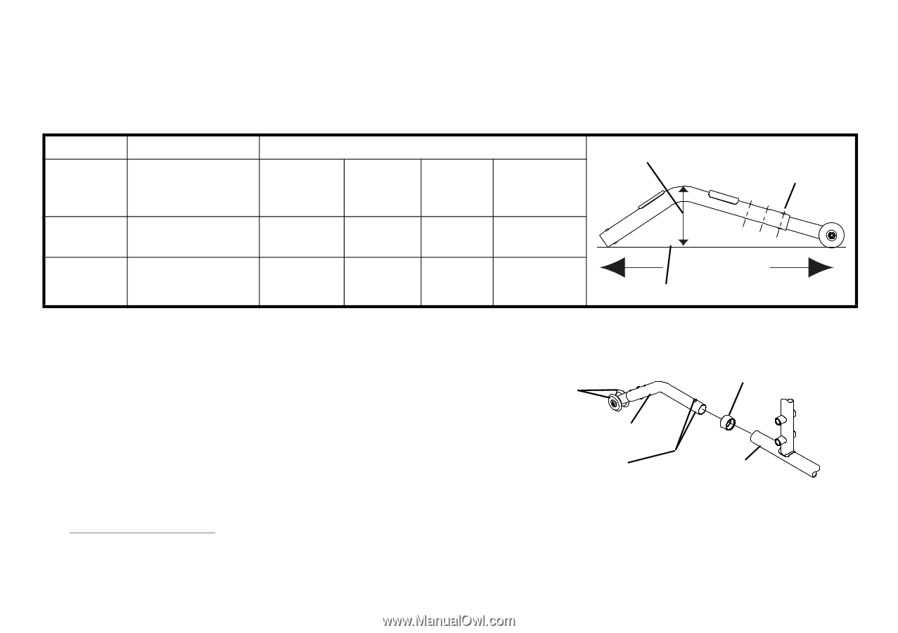
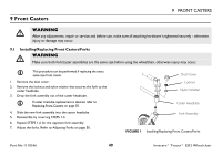
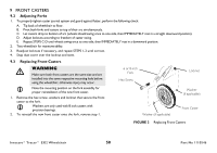
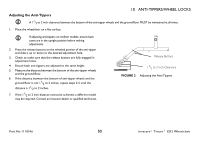
10 ANTI-TIPPERS/WHEEL LOCKS Installing Anti-Tippers To ensure the correct model anti-tipper is used refer to chart below. Measurements for anti-tippers are approximate and are taken with extension tube in bottom hole position. MODEL SEAT-TO-FLOOR HEIGHT (IN INCHES) ANTI-TIPPER (MEASUREMENTS IN INCHES) LENGTH HEIGHT MODEL PART NO. Anti-Tipper Height Bottom Position TRACER EX2 TRACER EX2 FF 17 1/2 to 19 1/2 21 131/2 12 31/2 1360 1058836 23/4 9758 1086190 Anti-Tipper Length Flat Surface 1. Press the release buttons and insert the anti-tippers with the anti-tipper wheels pointing toward the ground/floor into the wheelchair frame tubing. 2. Ensure that the release button of the anti-tipper fully protrudes out of the hole in the bottom of the wheelchair frame tubing. 3. Place the wheelchair on a flat surface. 4. Measure the distance between the bottom of the anti-tipper wheels and the ground/floor. Anti-Tipper Wheels Anti-Rattle A 11/2 to 2 inch clearance between the bottom of the anti-tipper wheels and the ground/floor MUST be maintained at all times. Anti-Tipper Release Buttons Rear Frame Tubing 5. If the distance between the bottom of anti-tipper wheels and the ground/floor is not 11/2 to 2 inches, adjust anti-tippers. Refer to Adjusting the Anti-Tippers on page 53. FIGURE 1 Installing Anti-Tippers Invacare® Tracer™ EX2 Wheelchair 52 Part No 1110546
-
 1
1 -
2
-
3
-
4
-
5
-
6
-
7
-
8
-
9
-
10
-
11
-
12
-
13
-
14
-
15
-
16
-
17
-
18
-
19
-
20
-
21
-
22
-
23
-
24
-
25
-
26
-
27
-
28
-
29
-
30
-
31
-
32
-
33
-
34
-
35
-
36
-
37
-
38
-
39
-
40
-
41
-
42
-
43
-
44
-
45
-
46
-
 47
47 -
 48
48 -
 49
49 -
 50
50 -
 51
51 -
 52
52 -
 53
53 -
 54
54 -
 55
55 -
 56
56 -
 57
57 -
58
-
59
-
60
-
61
-
62
-
63
-
64
 |
 |