JVC DLA-HD250PRO Instruction Manual - Page 55
Mounting this Unit, Precautions for Mounting
 |
View all JVC DLA-HD250PRO manuals
Add to My Manuals
Save this manual to your list of manuals |
Page 55 highlights
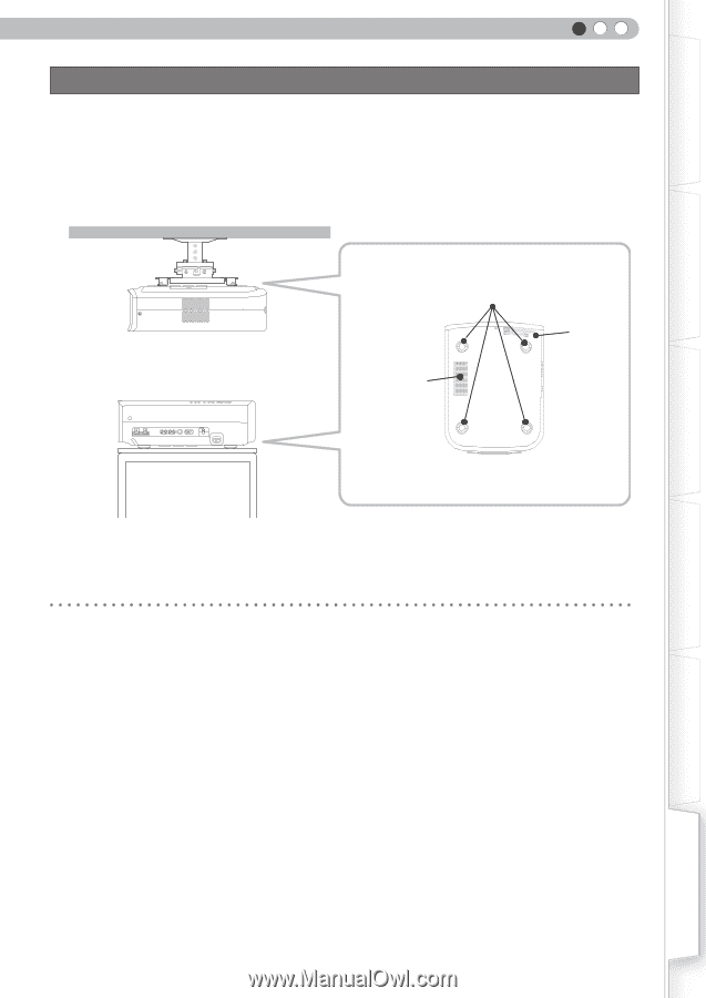
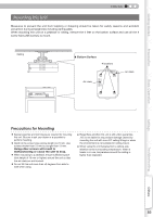
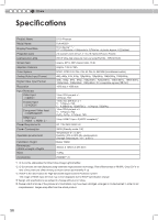
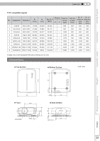
Getting Started ENGLISH Mounting this Unit Measures to prevent the unit from toppling or dropping should be taken for safety reasons and accident prevention during emergencies including earthquakes. When mounting this unit on a pedestal or ceiling, remove the 4 feet on the bottom surface and use all the 4 screw holes (M5 screws) to mount. Ceiling ■ Bottom Surface 4 locations Air inlets Air inlets Preparation Basic Operation Settings Troubleshooting Precautions for Mounting ● Special expertise and techniques are required for mounting this unit. Be sure to ask your dealer or a specialist to perform mounting. ● Depth of the screw holes (screw length) is 23 mm. Use screws shorter than 23 mm but longer than 13 mm. Using other screws will result in malfunctioning or cause the unit to drop. ● When mounting to a pedestal, ensure sufficient space (foot height of 10 mm or higher) around the unit so that the air inlets are not blocked. ● Do not tilt this unit more than ±5 degrees from side to side when using. ● Regardless whether the unit is still under guarantee, JVC is not liable for any product damage caused by mounting the unit with non-JVC ceiling fittings or when the environment is not suitable for ceiling-mount. ● When using the unit hanging from a ceiling, pay attention to the surrounding temperature. When a heater is in use, temperature around the ceiling is higher than expected. Others 55
-
 1
1 -
2
-
3
-
4
-
5
-
6
-
7
-
8
-
9
-
10
-
11
-
12
-
13
-
14
-
15
-
16
-
17
-
18
-
19
-
20
-
21
-
22
-
23
-
24
-
25
-
26
-
27
-
28
-
29
-
30
-
31
-
32
-
33
-
34
-
35
-
36
-
37
-
38
-
39
-
40
-
41
-
42
-
43
-
44
-
45
-
46
-
47
-
48
-
49
-
 50
50 -
 51
51 -
 52
52 -
 53
53 -
 54
54 -
 55
55 -
 56
56 -
 57
57 -
 58
58 -
 59
59 -
 60
60 -
61
-
62
-
63
-
64
-
65
-
66
-
67
-
68
-
69
-
70
-
71
-
72
-
73
-
74
-
75
-
76
-
77
-
78
-
79
-
80
-
81
-
82
-
83
-
84
-
85
-
86
-
87
-
88
-
89
-
90
-
91
-
92
-
93
-
94
-
95
-
96
-
97
-
98
-
99
-
100
-
101
-
102
-
103
-
104
-
105
-
106
-
107
-
108
-
109
-
110
-
111
-
112
-
113
-
114
-
115
-
116
-
117
-
118
-
119
-
120
-
121
-
122
-
123
-
124
-
125
-
126
-
127
-
128
-
129
-
130
-
131
-
132
-
133
-
134
-
135
-
136
-
137
-
138
-
139
-
140
-
141
-
142
-
143
-
144
-
145
-
146
-
147
-
148
-
149
-
150
-
151
-
152
-
153
-
154
-
155
-
156
-
157
-
158
-
159
-
160
-
161
-
162
-
163
-
164
-
165
-
166
-
167
-
168
-
169
-
170
-
171
-
172
-
173
 |
 |