JVC DT-V17G15Z Instruction Manual - Page 30
Specifications cont
 |
View all JVC DT-V17G15Z manuals
Add to My Manuals
Save this manual to your list of manuals |
Page 30 highlights
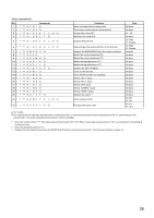
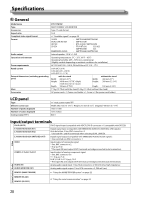
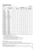
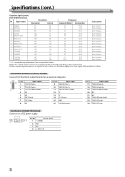
Specifications (cont.) Computer signals (preset) DVI-D (HDCP) terminals No. Signal name Resolution Horizontal Vertical Frequency Horizontal (kHz) Vertical (Hz) Scan system 1 VGA60 640 480 31.5 59.9 Non-interlace 2 WVGA60 852 480 31.5 59.9 Non-interlace 3 SVGA60 800 600 37.9 60.3 Non-interlace 4 XGA60 1024 768 48.4 60.0 Non-interlace 5 WXGA (1280) 1280 768 47.8 60.0 Non-interlace 6 WXGA+60 1440 900 55.9 60.0 Non-interlace 7 SXGA60 1280 1024 64.0 60.0 Non-interlace 8 WSXGA+60 1680 1050 65.2 60.0 Non-interlace 9 UXGA60 *1 1600 1200 75.0 60.0 Non-interlace 10 WUXGA60 *1 1920 1200 74.0 60.0 Non-interlace 11 720/60p 1280 720 45.0 60.0 Non-interlace 12 1080/60p 1920 1080 67.5 60.0 Non-interlace 13 720/50p 1280 720 37.5 50.0 Non-interlace 14 1080/50p 1920 1080 56.25 50.0 Non-interlace *1 In 1:1 mode, the top and bottom of the screen will be hidden. ● Even for a preset signal, picture may not be normally displayed depending on the signal timing. ● When a preset signal comes in, the signal format is shown on the status display. For other signals, the resolution is shown. Specification of the DVI-D (HDCP) terminal Connect it to the DVI-D output terminal on a personal computer. Pin No. Input signal 1 T.M.D.S Data 2- 2 T.M.D.S Data 2+ 3 T.M.D.S Data 2 shield 4 NC 5 NC 6 DDC Clock 7 DDC Data 8 NC Pin No. Input signal 9 T.M.D.S Data 1- 10 T.M.D.S Data 1+ 11 T.M.D.S Data 1 shield 12 NC 13 NC 14 +5 V Power 15 GND 16 Hot Plug Detect Pin No. Input signal 17 T.M.D.S Data 0- 18 T.M.D.S Data 0+ 19 T.M.D.S Data 0 shield 20 NC 21 NC 22 T.M.D.S Clock shield 23 T.M.D.S Clock+ 24 T.M.D.S Clock- Specification of the DC IN terminal Connect it to a DC power supply. Pin No. Input signal 1 - (GND) 2 NC 3 NC 4 + (DC 12V) 30
-
 1
1 -
2
-
3
-
4
-
5
-
6
-
7
-
8
-
9
-
10
-
11
-
12
-
13
-
14
-
15
-
16
-
17
-
18
-
19
-
20
-
21
-
22
-
23
-
24
-
 25
25 -
 26
26 -
 27
27 -
 28
28 -
 29
29 -
 30
30 -
 31
31 -
 32
32
 |
 |
