JVC KW-V11 Instruction Manual - Page 48
Connection - remote
 |
View all JVC KW-V11 manuals
Add to My Manuals
Save this manual to your list of manuals |
Page 48 highlights
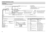
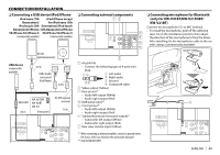
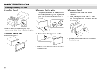
CONNECTION/INSTALLATION Connection R Connecting wires to terminals 10 A fuse USB terminal (0.8 m): See page 49.*1 See page 49. *1 Only for KW-V41BT. *2 Only for KW-V215DBT. *3 For KW-V41BT/KW-V21BT/KW-V11: The appearance of the aerial terminal is different from the illustration. *4 Only for KW-V41BT/KW-V215DBT/KW-V21BT. *2 Connect the aerial cord to the aerial terminal.*3 Connect to the vehicle's reverse Purple with white stripe (Reverse sensor wire) lamp harness when using the optional rear view camera. 3 Connect to the vehicle's parking brake detection switch harness. • For best safety, be sure to connect the parking sensor. 1 See page 49.*4 Light green (Parking sensor wire) Light blue with yellow stripe (Steering remote control wire) To the OE remote adapter matching your car • If no connections are made, do not let the cable come out from the tab. Yellow (Battery wire) Red (Ignition wire) Red (A7) Yellow (A4) Connector A Connector B 48 Connecting the ISO connectors Pin Color and functions of Connector A and B You may need to modify the wiring of the A4 Yellow Battery supplied wiring harness as illustrated below. A5 Blue with white stripe Power control Red (Ignition wire) Red (A7) A6 Orange with white stripe Dimmer A7 Red Ignition (ACC) Unit Yellow (Battery wire) Default wiring Vehicle Yellow (A4) A8 Black Ground connection B1 Purple Right speaker ª (rear) B2 Purple with black stripe Right speaker · (rear) B3 Gray Right speaker ª (front) B4 Gray with black stripe Right speaker · (front) B5 White Left speaker ª (front) B6 White with black stripe Left speaker · (front) B7 Green Left speaker ª (rear) B8 Green with black stripe Left speaker · (rear)
-
 1
1 -
2
-
3
-
4
-
5
-
6
-
7
-
8
-
9
-
10
-
11
-
12
-
13
-
14
-
15
-
16
-
17
-
18
-
19
-
20
-
21
-
22
-
23
-
24
-
25
-
26
-
27
-
28
-
29
-
30
-
31
-
32
-
33
-
34
-
35
-
36
-
37
-
38
-
39
-
40
-
41
-
42
-
 43
43 -
 44
44 -
 45
45 -
 46
46 -
 47
47 -
 48
48 -
 49
49 -
 50
50 -
 51
51 -
 52
52 -
 53
53 -
54
-
55
-
56
-
57
-
58
-
59
-
60
-
61
-
62
-
63
-
64
-
65
-
66
-
67
-
68
-
69
-
70
-
71
-
72
-
73
-
74
-
75
-
76
-
77
-
78
-
79
-
80
-
81
-
82
-
83
-
84
-
85
-
86
-
87
-
88
-
89
-
90
-
91
-
92
-
93
-
94
-
95
-
96
-
97
-
98
-
99
-
100
-
101
-
102
-
103
-
104
-
105
-
106
-
107
-
108
-
109
-
110
-
111
-
112
-
113
-
114
-
115
-
116
-
117
-
118
-
119
-
120
-
121
-
122
-
123
-
124
-
125
-
126
-
127
-
128
-
129
-
130
-
131
-
132
-
133
-
134
-
135
-
136
-
137
-
138
-
139
-
140
-
141
-
142
-
143
-
144
-
145
-
146
-
147
-
148
-
149
-
150
-
151
-
152
-
153
-
154
-
155
-
156
-
157
-
158
-
159
-
160
-
161
-
162
-
163
-
164
-
165
-
166
-
167
-
168
-
169
-
170
-
171
-
172
-
173
-
174
-
175
-
176
-
177
-
178
-
179
-
180
-
181
-
182
-
183
-
184
-
185
-
186
-
187
-
188
-
189
-
190
-
191
-
192
-
193
-
194
-
195
-
196
-
197
-
198
-
199
-
200
-
201
-
202
-
203
-
204
-
205
-
206
-
207
-
208
-
209
-
210
-
211
-
212
-
213
-
214
-
215
-
216
-
217
-
218
-
219
-
220
-
221
-
222
-
223
-
224
-
225
-
226
-
227
-
228
-
229
-
230
-
231
-
232
-
233
-
234
-
235
-
236
-
237
-
238
-
239
-
240
-
241
-
242
 |
 |
