JVC TKC215V12U Instructions - Page 10
Mounting the Camera to the, Ceiling continued
 |
View all JVC TKC215V12U manuals
Add to My Manuals
Save this manual to your list of manuals |
Page 10 highlights
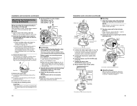
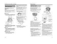
Installation and connection (continued) Mounting the Camera to the Ceiling (continued) Embedding the camera to the ceiling * Make use of a ceiling material with a thickness between 9.5 mm to 22 mm. Ⅵ Setup 1. Open a hole in the ceiling. (R120 mm) 2. Draw the fall prevention wire mounted to the ceiling slab and the cable out from the ceiling in advance. CAUTION: ● Select a suitable safety cable based on length, strength, location, material (insulation property), etc. ● Use a ring on the fall prevention wire for mounting to the camera unit with an internal diameter of at least R3.1 mm or and not larger than R5.5 mm, and an external diameter that is not larger than R9 mm. 1. R120 mm 4. Remove the outer case. (This method does not require an outer case.) A Loosen the outer case fastening screw with a screwdriver B To remove, turn the camera unit in the anti- clockwise direction 5. Dismantle the supplied fall prevention wire Unfasten the mounting screw for the fall prevention wire at the rear of the camera unit 6. Loosen the pan fastening screw. CAUTION: Moving the lens unit without loosening the pan fastening screw may damage the lens unit. 7. Set the switches for video images. (TK-C215V4 A pg. 10) (TK-C215V12 A pg. 12) (TK-C210FW A pg. 14) 4. Pan fastening 7. A Screw Fall prevention wire (not supplied) Approx. 100 mm 2. Video signal cable Alarm signal cable *TK-C215V12 only Power supply cable 3. Remove the dome cover. As illustrated in the diagram, hold the dome ring such that the position mark comes between the thumb and index finger. Turn the ring in the anti-clockwise direction to remove. 3. 4. B Camera Fastening Screw 5. Washer *TK-C215V4 is used in the above illustration Dome Ring 18 Position mark Ⅵ Connecting 1. Attach the fall prevention wire to the camera, followed by attaching it to the ceiling slab (Fall prevention wire is not included.) 2. Connect the video signal cable. (A pg. 14) Lower the cover and connect the connectors. Upon connecting, cover the connectors using the protection cover. 3. Connect the input power supply cable. (A pg. 15) 4. Install the Ferrite core (TK-C210FW only) (A pg. 14) 5. Connect the alarm cable. (TK-C215V12 only) (A pg. 15) 6. Wrap insulation tape around cables. 7. Insert the camera unit into the ceiling hole. Ⅵ Mounting 1. Align j with the shooting direction when mounting the camera. 2. Fasten the camera. (x3 locations) A Press the screw head of the clamping bracket all the way in using a cross screwdriver. B With the screw pressed in using the screwdriver, turn about 90 Њ in the clockwise direction, followed by pulling out the screwdriver. C The clamping bracket is attached to the ceiling and the camera fastened. NOTE: Dismantle the camera upon turning the screw heads of the ceiling mount bracket (x3) by 90 Њ in the anti-clockwise direction. 7. Fall preven- tion wire (not supplied) 2. Protection cover 1. Alarm signal cable (TK-C215V12 only) 3.5. Solder or crimp Insulation tape Wrap with tape 6. Input power supply cable *TK-C215V12 is used in the above illustration 1. B UPFRONT Align with shooting direction 2. A *TK-C215V4 is used in the above illustration Ⅵ Adjusting Images After mounting is completed, adjust the images while checking the actual image. (A pg. 23 AAdjusting ImagesB) 19
-
 1
1 -
2
-
3
-
4
-
 5
5 -
 6
6 -
 7
7 -
 8
8 -
 9
9 -
 10
10 -
 11
11 -
 12
12 -
 13
13 -
 14
14 -
 15
15 -
16
 |
 |
