JVC TKC215V12U Instructions - Page 9
System diagram, Mounting the Camera to the, Ceiling - digital video camera
 |
View all JVC TKC215V12U manuals
Add to My Manuals
Save this manual to your list of manuals |
Page 9 highlights
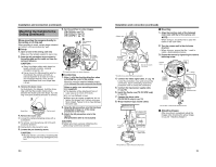
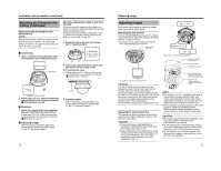
Installation and connection (continued) System diagram TK-C215V4 Video signal Power TK-C210FW Video signal Power TK-C215V12 Video signal Power Alarm signal (METAL CONTACT) Power Unit DC 12 V or AC 24 V (Class 2) VIDEO IN AUDIO IN 1 2 3 4 VIDEO IN THRU OUT SCSI RS-232C LAN UPS 5 6 7 8 9 10 11 12 13 14 15 16 AUDIO OUT 1 2 VIDEO OUT 1 2 CAUTION RISK OF ELECTRIC SHOCK DO NOT OPEN AVIS:RISQUE DE CHOC ELECTRIQ 1 4/ 16 5 8 1 3 5 7 9 11 13 15 RST COM IN IN EXT REC CLK SER 2 4 6 8 10 12 14 16 OUT WAR RST REC COM ALARM OUT OUT OUT 9 12 13 16 EE OUT Digital Video Recorder etc. VIDEO OUT AC IN (220V-240V ) SIGNAL GND MONITOR NOTE: ● Turn OFF the power supply to all equipment to be used before making connections. ● Read the Instruction Manual for each piece of equipment to be used before making connections. CAUTION: Power consumption of TK-C210FW/TK-C215V4/ TK-C215V12 are different from one another. When installing a mixture of these models, select a cable length according to the power consumption of each model. Alternatively, install based on the model with the highest power consumption. Mounting the Camera to the Ceiling Getting Started CAUTION: ● When mounting the camera to the ceiling, ensure to wear safety glasses to protect the eye from any falling object. ● Attachment of a embedded cover in the ceiling (recess bracket) may be mandatory in certain regions. If this is so, ensure that the embedded cover (recess bracket) is securely attached before installing the camera. ● Please refer to the instruction manual for the cover in use for details on installation of the embedded cover (recess bracket). ● For more detail, please contact the JVC. Selecting a mounting method Select a method for mounting the camera according to the intended purpose. ‹ AEmbedding the camera to the ceilingB (A pg. 18) ‹ AWhen mounting the camera directly to the ceiling or on the wallB (A pg. 20) ‹ AWhen mounting the camera to the electrical boxB (A pg. 22) ‹ AMount by allowing the cable to exit from the sideB (A pg. 22) Ceiling Embedded Cover in Ceiling (recess bracket) 16 17
-
 1
1 -
2
-
3
-
 4
4 -
 5
5 -
 6
6 -
 7
7 -
 8
8 -
 9
9 -
 10
10 -
 11
11 -
 12
12 -
 13
13 -
 14
14 -
15
-
16
 |
 |
