JVC TKC215V12U Instructions - Page 14
Adjusting Images, continued, Mounting the Dome Cover, White-spot correction
 |
View all JVC TKC215V12U manuals
Add to My Manuals
Save this manual to your list of manuals |
Page 14 highlights
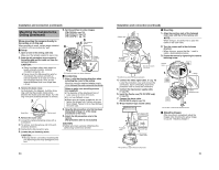
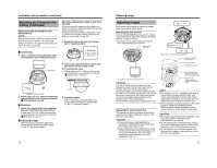
Adjusting Image (continued) POSITION ZOOM/FOCUS SELECT FAR IRIS Adjusting Images (continued) ‹ Registering alarm position For registering the angle of view during monitoring when there is an alarm input. 4. 2.,3. 1.,5. WIDE TELE NEAR L [MEMORY] LEVEL H ALARM POSITION WHT.BAL. 2 R 4 B 1 2 3 4 5 6 7 8 LL PHASE RESET/[SPOT] Mounting the Dome Cover After setting is complete, mount the dome cover. Position mark 1. 1. Check that the [ALARM POSITION] indicator light is turned on. Registration of alarm position is enabled. ● Press the [POSITION SELECT] button if the [ALARM POSITION] indicator light is off. 2. Adjust the image size. (A pg. 25) 3. Press the [MEMORY] button for 2 seconds or longer. The [ALARM POSITION] indicator light blinks for 3 times (green) Ň ALARM position registration is completed 4. Adjust the brightness. (A pg. 25) 5. Press the [POSITION SELECT] button. The camera returns to the home position NOTE: ● Be sure to return the camera to the home position after registration of the alarm position is completed. In addition to pressing the [POSITION SELECT] button, you can also use the power ON/OFF button to return the camera to the home position. ● To check images at the registered home position or alarm position, press the [POSITION SELECT] button. Press this button to switch between the image at the home and alarm positions. 1. Mount the dome cover. Align the position marks on the camera unit and dome cover, followed by pressing in directly to mount the cover. CAUTION: Press the dome over until a "click" sound is heard. Check that the cover is firmly mounted. Failure to mount the cover firmly may cause this cover to fall off. POSITION ZOOM/FOCUS SELECT FAR WIDE NEAR ALARM POSITION 2 4 1 2 3 4 5 White-spot correction As a general characteristic unique to CCDs, white-spots may appear on the screen with age. In order to reduce this phenomenon, this unit is equipped with a white-spot correction feature. Switch on the camera power supply and wait for at least 30 minutes. (Not available on TK-C210FW) ‹ TK-C215V4 RESET/[SPOT] [SPOT] button B R IRIS TELE LL PHASE 1 2 3 4 5 6 7 8 O N2 4 WHT. BAL. ‹ TK-C215V12 L [MEMORY] LEVEL H WHT.BAL. R B 6 7 8 LL PHASE RESET/[SPOT] Function selection switch 8 [SPOT] button Function selection switch 8 1. Remove the dome cover. 2. Cover the lens surface using a black sheet of paper, etc. so that light does not enter the lens. 3. Set the function selection switch 8 to [SPOT]. (A pg. 11, 13) 4. Press and hold the SPOT CORRECTION button for more than 2 seconds. ● White-spot correction will start. Correction may take several seconds for completion. NOTE: ● Maximum correction: less than 16 to 32 spots ● The white-spot correction feature of this unit does not guarantee the correction of all white spots. Depending on the characteristic of white spots, correction may not be possible. ● When performing white-spot correction, accurate data may not be achieved in case of highly detailed pixels since correction is made using the information of surrounding pixels. ● The result of white-spot correction is maintained until the next correction is performed. 26 27
-
 1
1 -
2
-
3
-
4
-
5
-
6
-
7
-
8
-
 9
9 -
 10
10 -
 11
11 -
 12
12 -
 13
13 -
 14
14 -
 15
15 -
 16
16
 |
 |
