JVC TKC215V12U Instructions - Page 8
Setting the Lens and, Switches TK-C210FW, About Connection Cables
 |
View all JVC TKC215V12U manuals
Add to My Manuals
Save this manual to your list of manuals |
Page 8 highlights
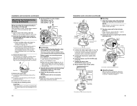
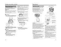
Installation and connection Setting the Lens and Switches (TK-C210FW) Set the video setting switches on the camera unit before mounting it. To set the switches, use a fine-tipped screwdriver. About Connection Cables The maximum connection distance varies with the type of cable used. Please refer carefully to the table for each cable during connection. * Be sure to turn off the power of devices before connecting cables. BLC ON OFF A 1. 2. To video Signal Cable To DC 12 V or AC 24 V Power Supply To Alarm Signal Cable (TK-C215V12) Only A Function selection switches 1. [BLC] Backlight compensation switch. When the object is placed against the light, setting this to AONB increases the iris aperture by 1 stop and the object will appear clearer. (Default setting: OFF) 2. Service switch. Ensure to set to AONB. Video signal cables Connect the coaxial cables (BNC) to the video signal output connector (BNC). Cable RG-59 RG-6 RG-11 Maximum extension (No cable compensator) 200 m 350 m 450 m Installing the Ferrite core (TK-C210FW only) In order to reduce the influence to the screen caused by the noise induced from the cable, wind both Video signal cable and Input power supply cable once to the supplied Ferrite core. To power supply To video Signal Cable To Camera Ferrite Core DC 12 V or AC 24 V power supply cable Connect the DC 12 V or the AC 24 V power supply to the DC 12 V/AC 24 V terminals on the terminal board. To prevent connection errors or a cable disconnection, we recommend the use of lug plates for the connections. The following table shows the connection distances and connection cables provided that 2-conductor VVF cables (vinyl-insulated vinyl sheath cables) are used. Conductor diameter (mm) TK-C210FW Maximum extension TK-C215V4 Maximum extension TK-C215V12 Maximum extension DC12V AC24V DC12V AC24V DC12V AC24V R 1.0 mm (AWG18) 80 m (260ft) 210 m (680ft) 50 m (160ft) 130 m (420ft) 30 m (90ft) 80 m (260ft) R 1.6 mm (AWG14) 210 m (680ft) 540 m (1700ft) 140 m (450ft) 350 m (1100ft) 80 m (260ft) 210 m (680ft) R 2.0 mm (AWG12) 340 m (1100ft) 860 m (2800ft) 220 m (720ft) 550 m (1800ft) 130 m (420ft) 340 m (1100ft) CAUTION: ● If thin cables are used (i.e. with a high resistance), a significant voltage drop will occur when the unit is at its maximum power consumption. Either use a thick cable to restrict the voltage drop at the camera side to below 10 %, or place the power supply near to the camera. When the voltage is low, the protection circuit within the camera may be triggered and the power of the camera may turn off automatically. ● Do not allow input from both a DC 12 V and AC 24 V power supply at the same time. ● When using a DC 12 V power supply, ensure that the polarities of the cable are correct. ● The AC 24 V power supply should conform to the following: U-type: Class 2 only E-type: Isolated power supply only Electrical Specifications of Alarm Input Terminals (TK-C215V12 only) ● To prevent penetration of noise in the internal circuitry, apply a non-voltage contact signal to the ALARM input terminal. Never apply a voltage. ● Apply an alarm signal for at least 200 ms. If it is shorter, it is not guaranteed that the signal will be recognized as an alarm signal. ● Under the alarm status (status when the metal contact is "make"), select the contact or connecting wire such that the maximum wire resistance between the ALARM IN and ALARM GND is within 150 K. ALARM IN ALARM GND ‹ Polarity of alarm signals ALARM INPUT SHORT (CONTACT) OPEN ALARM NORMAL (HOME POSITION) 14 15
-
 1
1 -
2
-
 3
3 -
 4
4 -
 5
5 -
 6
6 -
 7
7 -
 8
8 -
 9
9 -
 10
10 -
 11
11 -
 12
12 -
 13
13 -
14
-
15
-
16
 |
 |
