JVC TKC215V12U Instructions - Page 12
Mounting the Camera to the, Ceiling continued, Adjusting Images
 |
View all JVC TKC215V12U manuals
Add to My Manuals
Save this manual to your list of manuals |
Page 12 highlights
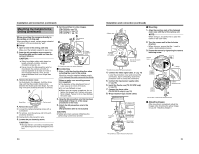
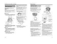
Installation and connection (continued) Mounting the Camera to the Ceiling (continued) When mounting the camera to the electrical box NOTE: Before mounting the camera to electrical boxes, please consult your nearby JVC authorized dealer for details on the type of electrical box for which mounting is possible. Mount by allowing the cable to exit from the side When mounting the camera to the ceiling or a wall, it is possible to guide the cable from the side without opening any holes. The basic mounting method is identical to steps in AWhen mounting the camera directly to the ceiling or on the wallB (A pg. 20). 1. Break the cable extraction hole using a pair of long-nose pliers Ⅵ Connecting 1. Align j with the shooting direction when mounting the cover to the electrical box. Adaptor ring 2. Pull out the cable from the extraction hole and mount it to the ceiling or wall 3. Connecting the cable Follow steps 4 to 7 of AWhen mounting the camera directly to the ceiling or on the wallB (Ⅵ Connecting) (A pg. 21) UPFRONT Cable Align with shooting direction 2. Follow steps 2 to 7 of AWhen mounting the camera directly to the ceiling or on the wallB (Ⅵ Connecting) (A pg. 20). Ⅵ Mounting 1. Attach the camera to the outer case that has been fastened to the electrical box. Follow steps 1 to 3 of AWhen mounting the camera directly to the ceiling or on the wallB (Ⅵ Mounting) (A pg. 21) Ⅵ Adjusting Images After mounting is completed, adjust the images while checking the actual image. (A pg. 23 AAdjusting ImagesB) 4. Adjusting Images After mounting is completed, adjust the images while checking the actual image. (A pg. 23 AAdjusting ImagesB) 22 Adjusting Image Adjusting Images Upon mounting the camera, adjust the images while checking the actual image. Mounting the test monitor Connect the [MONITOR] terminal of this camera to a test monitor to adjust the camera's shooting direction, image and focus. * The power to the camera body must be ON when adjustments are performed. [MONITOR] Terminal Pan : ± 175 Њ Rotation : ± 175 Њ Tilt : ± 80 Њ *TK-C215V4 is used in the above illustration Camera's shooting direction mark Pan center mark Rotation center mark Test Monitor *TK-C215V4 is used in the above illustration CAUTION: The TK-C210FW monitor produces a high impedance output. Do not terminate the test monitor. Allow it to remain open during connection. When a test monitor that cannot be left open is connected to this terminal, the picture level when connected to the video signal output connector may deteriorate and appear dark. However, this is not a malfunction. TK-C215V4/V12 output at an impedance of 75 K. Adjusting the camera direction The camera unit can be adjusted horizontally or vertically and rotated. Adjust the camera in the direction of the object. CAUTION: ● Please discharge a static electricity by touching to a [MONITOR] Terminal by hand before adjust the angle of view. ● Before adjusting the shooting direction of the camera, ensure that the pan fastening screw is loosened. Moving the lens unit without loosening the pan fastening screw may damage the lens unit. UP FOR S E RVICE WB ET 1 AGC OFF ON 2 CABLE SHORT MID LONG 3 LENGTH 4 WHT. BAL. ATW AWB O N 4 FOCUS ADJUST 5 BLC OFF ON 6 DAY/NIGHT OFF ON 7 SHUTTER 1 /60 1 /100 8 RESEVED SET TO OFF SEE INSTRUCTION MANUAL Pan fastening screw : Be sure to loosen the screw before adjusting. Rotation knob : Always adjust the rotation by holding this knob. NOTE: ● Pan rotation of ±175 Њ is possible from each of the camera's shooting direction mark, pan center mark and rotation center mark. When adjusting the rotation, do not hold the lens unit. Always adjust by holding the rotation knob. ● When using the camera at locations with strong vibration, stabilize by tightening the tile fastening screw and pan fastening screw to prevent distortion of the camera's field angle. CAUTION: ● Moving the camera beyond its adjustable range may cause failure in maintaining the performance of this camera. ● As this camera has a wide tilt/rotation range, a part of this camera may appear on the screen depending on the field angle and orientation. ● Do not hold the lens unit when adjusting the direction of the camera. Applying force on the lens unit may damage it. 23
-
 1
1 -
2
-
3
-
4
-
5
-
6
-
 7
7 -
 8
8 -
 9
9 -
 10
10 -
 11
11 -
 12
12 -
 13
13 -
 14
14 -
 15
15 -
 16
16
 |
 |
