Kenmore 7800 Installation Instructions - Page 8
Gas Oonne< t
 |
UPC - 883049211312
View all Kenmore 7800 manuals
Add to My Manuals
Save this manual to your list of manuals |
Page 8 highlights
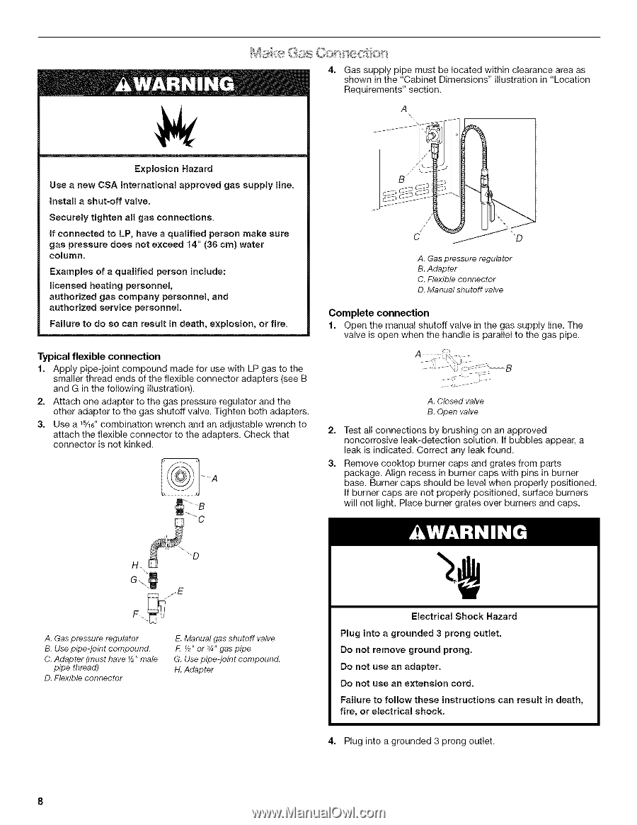
Gas Oonne< t on Gas supply pipe must be located within clearance area as shown in the "Cabinet Dimensions" illustration in "Location 4. Requirements" section. A Explosion Hazard Use a new CSA International approved gas supply line. Install a shut-off valve. Securely tighten all gas connections. if connected to LP, have a qualified person make sure gas pressure does not exceed 14" (36 cm) water column. Examples of a qualified person include: licensed heating personnel, authorized gas company personnel, and authorized service personnel. Failure to do so can result in death, explosion, or fire. Typical flexible connection 1. Apply pipe-joint compound made for use with LP gas to the smaller thread ends of the flexible connector adapters (see B and G in the following illustration). 2. Attach one adapter to the gas pressure regulator and the other adapter to the gas shutoff valve. Tighten both adapters. 3. Use a 1%6"combination wrench and an adjustable wrench to attach the flexible connector to the adapters. Check that connector is net kinked. A. Gas pressure regulator B. Adapter C. Flexible connector D. Manual shutoff valve Complete connection 1. Open the manual shutoff valve in the gas supply line. The valve is open when the handle is parallel to the gas pipe. A. Closed valve B. Open valve 2. Test all connections by brushing on an approved noncorrosive leak-detection solution. If bubbles appear, a leak is indicated. Correct any leak found. 3. Remove cooktop burner caps and grates from parts package. Align recess in burner caps with pins in burner base. Burner caps should be level when properly positioned. If burner caps are not properly positioned, surface burners will not light. Place burner grates over burners and caps. H\ A. Gas pressure regulator B. Use pipe-joint compound. C. Adapter (must have Y2"male pipe thread) D. Flexible connector E. Manual gas shutoff valve F. _/2"or 3/4"gas pipe G. Use pipe-joint compound. H. Adapter Electrical Shock Hazard Plug into a grounded 3 prong outlet. Do not remove ground prong. Do not use an adapter. Do not use an extension cord. Failure to follow these instructions can result in death, fire, or electrical shock. 4. Plug into a grounded 3 prong outlet.
-
 1
1 -
2
-
 3
3 -
 4
4 -
 5
5 -
 6
6 -
 7
7 -
 8
8 -
 9
9 -
 10
10 -
 11
11 -
 12
12 -
 13
13 -
14
-
15
-
16
-
17
-
18
-
19
-
20
-
21
-
22
-
23
-
24
-
25
-
26
-
27
-
28
-
29
-
30
-
31
-
32
-
33
-
34
-
35
-
36
 |
 |