Kenmore 7952 Installation Instructions - Page 10
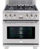
Kenmore 7952 - Pro 30 in. Dual Fuel Range Manual
 |
View all Kenmore 7952 manuals
Add to My Manuals
Save this manual to your list of manuals |
Page 10 highlights
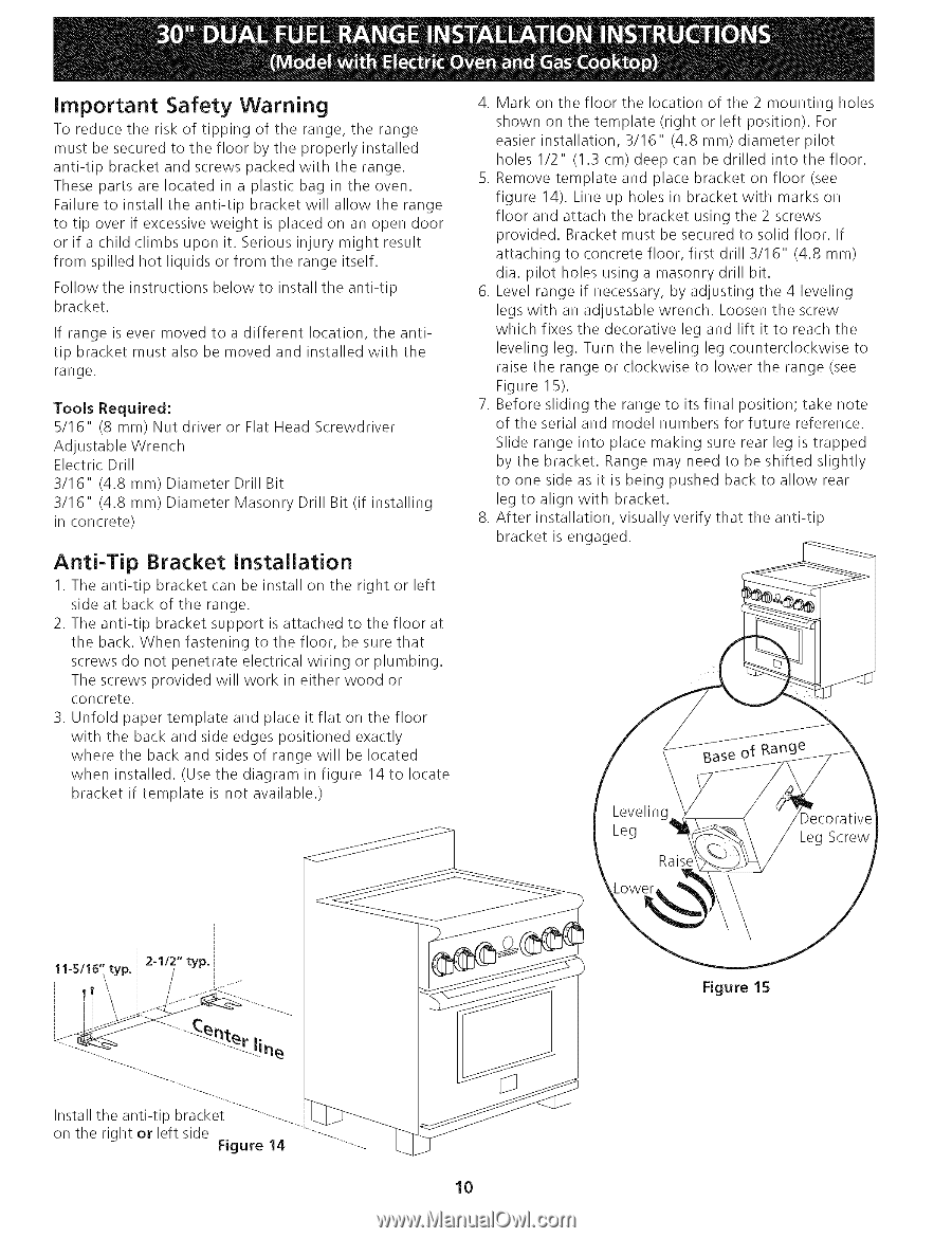
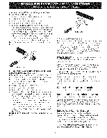
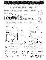
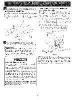
Important Safety Warning To reduce the risk of tipping of the range, the range must be secured to the floor by the properly installed anti-tip bracket and screws packed with the range. These parts are located in a plastic bag in the oven. Failure to install the anti-tip bracket will allow the range to tip over if excessive weight is placed on an open door or if a child climbs upon it. Serious injury might result from spilled hot liquids or from the range itself. Follow the instructions below to install the anti-tip bracket. If range is ever moved to a different location, the antitip bracket must also be moved and installed with the range. Tools Required: 5/16" (8 mm) Nut driver or Flat Head Screwdriver Adjustable Wrench Electric Drill 3/16" (4.8 mm) Diameter Drill Bit 3/16" (4.8 mm) Diameter Masonry Drill Bit (if installing in concrete) 4. Mark on the floor the location of the 2 mounting holes shown on the template (right or left position). For easier installation, 3/16" (4.8 mm) diameter pilot holes 1/2" (1.3 cm) deep can be drilled into the floor. 5. Remove template and place bracket on floor (see figure 14). Line up holes in bracket with marks on floor and attach the bracket using the 2 screws provided. Bracket must be secured to solid floor. If attaching to concrete floor, first drill 3/16" (4.8 mm) dia. pilot holes using a masonry drill bit. 6. Level range if necessary, by adjusting the 4 leveling legs with an adjustable wrench. Loosen the screw which fixes the decorative leg and lift it to reach the leveling leg. Turn the leveling leg counterclockwise to raise the range or clockwise to lower the range (see Figure 15). 7. Before sliding the range to its final position; take note of the serial and model numbers for future reference. Slide range into place making sure rear leg is trapped by the bracket. Range may need to be shifted slightly to one side as it is being pushed back to allow rear leg to align with bracket. 8. After installation, visually verify that the anti-tip bracket is engaged. Anti-Tip Bracket installation 1. The anti-tip bracket can be install on the right or left side at back of the range. 2. The anti-tip bracket support is attached to the floor at the back. When fastening to the floor, be sure that screws do not penetrate electrical wiring or plumbing. The screws provided will work in either wood or concrete. 3. Unfold paper template and place it flat on the floor with the back and side edges positioned exactly where the back and sides of range will be located when installed. (Use the diagram in figure 14 to locate bracket if template is not available.) Figure 15 !i% Install the anti-tip bracket ...on the right or left side Figure 14 10
-
 1
1 -
2
-
3
-
4
-
 5
5 -
 6
6 -
 7
7 -
 8
8 -
 9
9 -
 10
10 -
 11
11 -
 12
12 -
 13
13 -
 14
14 -
 15
15 -
16
-
17
-
18
-
19
-
20
-
21
-
22
-
23
-
24
 |
 |