Kenmore 7952 Installation Instructions - Page 6
Kenmore 7952 - Pro 30 in. Dual Fuel Range Manual
 |
View all Kenmore 7952 manuals
Add to My Manuals
Save this manual to your list of manuals |
Page 6 highlights
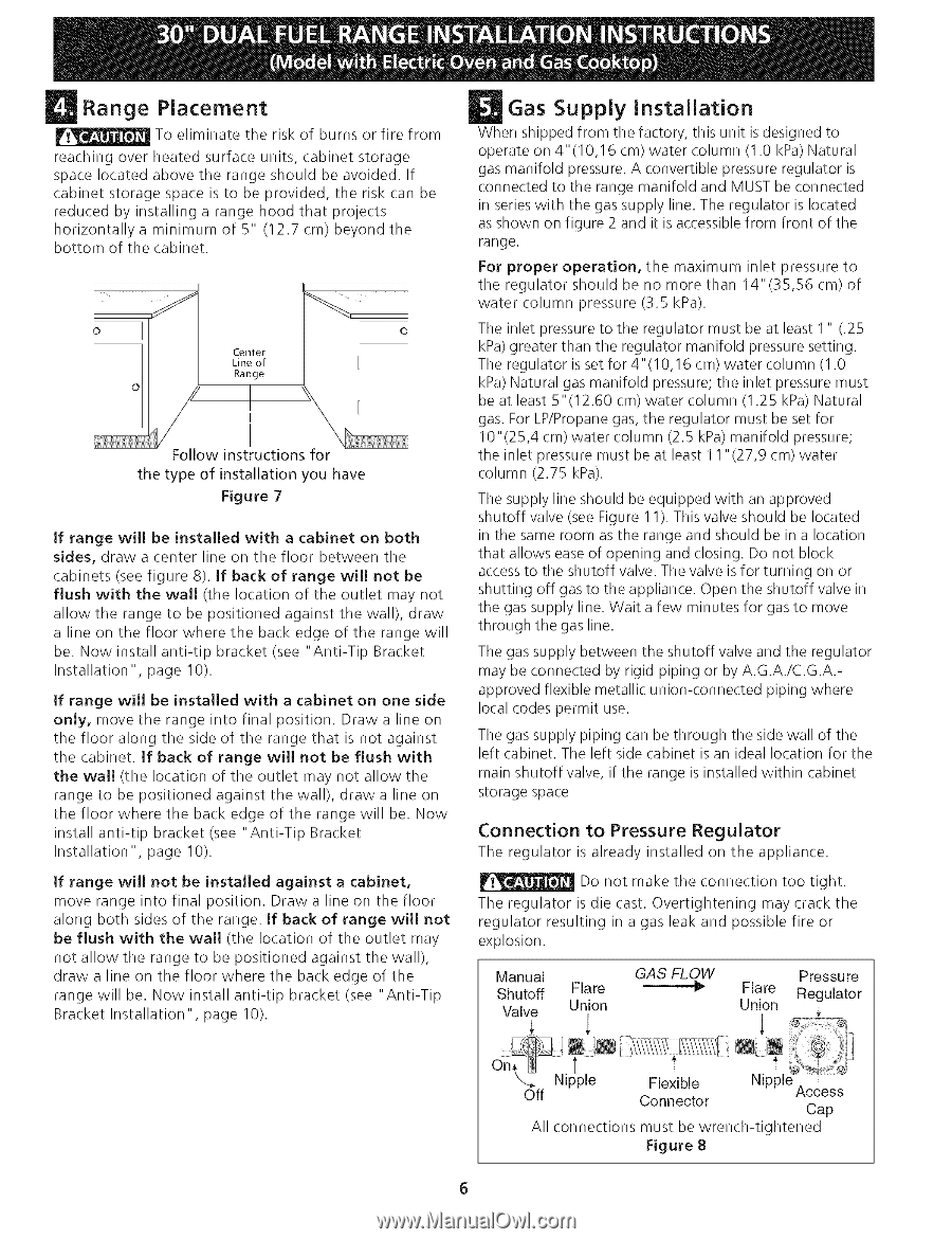
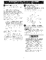
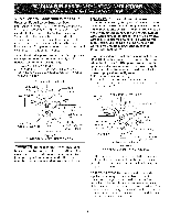
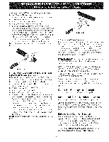
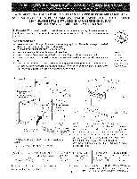
Range Placement To eliminate the risk of burns or fire from reaching over heated surface units, cabinet storage space located above the range should be avoided. If cabinet storage space is to be provided, the risk can be reduced by installing a range hood that projects horizontally a minimum of 5" (12.7 cm) beyond the bottom of the cabinet. Gas Supply Installation When shipped from the factory, this unit is designed to operate on 4"(10,16 cm) water column (1.0 kPa) Natural gas manifold pressure. A convertible pressure regulator is connected to the range manifold and MUST be connected in series with the gas supply line. The regulator is located as shown on figure 2 and it is accessible from front of the range. For proper operation, the maximum inlet pressure to the regulator should be no more than 14"(35,56 cm) of water column pressure (3.5 kPa). o Center Line of Range Follow instructions for the type of installation you have Figure 7 if range will be installed with a cabinet on both sides, draw a center line on the floor between the cabinets (see figure 8). If back of range will not be flush with the wall (the location of the outlet may not allow the range to be positioned against the wall), draw a line on the floor where the back edge of the range will be. Now install anti-tip bracket (see "Anti-Tip Bracket Installation", page 10). The inlet pressure to the regulator must be at least 1 " (.25 kPa) greater than the regulator manifold pressure setting. The regulator is set for 4"(10,16 cm) water column (1.0 kPa) Natural gas manifold pressure; the inlet pressure must be at least 5"(12.60 cm) water column (1.25 kPa) Natural gas. For LP/Propane gas, the regulator must be set for 10"(25,4 cm) water column (2.5 kPa) manifold pressure; the inlet pressure must be at least 11 "(27,9 cm) water column (2.75 kPa). The supply line should be equipped with an approved shutoff valve (see Figure 1 I). This valve should be located in the same room as the range and should be in a location that allows ease of opening and closing. Do not block access to the shutoff valve. The valve is for turning on or shutting off gas to the appliance. Open the shutoff valve in the gas supply line. Wait a few minutes for gas to move through the gas line. The gas supply between the shutoff valve and the regulator may be connected by rigid piping or by A.G.A./C.G.A.approved flexible metallic union-connected piping where local codes permit use. The gas supply piping can be through the side wall of the left cabinet. The left side cabinet is an ideal location for the main shutoff valve, if the range is installed within cabinet storage space Connection to Pressure Regulator The regulator is already installed on the appliance. Do not make the connection too tight. The regulator is die cast. Overtightening may crack the regulator resulting in a gas leak and possible fire or explosion. Manual Shutoff Valve GAS FLOW --,1_ Pressure Regulator + i If range will be installed with a cabinet on one side only, move the range into final position. Draw a line on the floor along the side of the range that is not against the cabinet. If back of range will not be flush with the wall (the location of the outlet may not allow the range to be positioned against the wall), draw a line on the floor where the back edge of the range will be. Now install anti-tip bracket (see "Anti-Tip Bracket Installation", page I0). if range will not be installed against a cabinet, move range into final position. Draw a line on the floor along both sides of the range. If back of range will not be flush with the wall (the location of the outlet may not allow the range to be positioned against the wall), draw a line on the floor where the back edge of the range will be. Now install anti-tip bracket (see "Anti-Tip Bracket Installation", page 10). Flare Union Flare Union " ot il N, Nipple Flexible Connector Nipple _ 1 Off Access Cap All connections must be wrench-tightened Figure 8 •t
-
 1
1 -
 2
2 -
 3
3 -
 4
4 -
 5
5 -
 6
6 -
 7
7 -
 8
8 -
 9
9 -
 10
10 -
 11
11 -
 12
12 -
13
-
14
-
15
-
16
-
17
-
18
-
19
-
20
-
21
-
22
-
23
-
24
 |
 |