Kenmore 7952 Installation Instructions - Page 4
Kenmore 7952 - Pro 30 in. Dual Fuel Range Manual
 |
View all Kenmore 7952 manuals
Add to My Manuals
Save this manual to your list of manuals |
Page 4 highlights
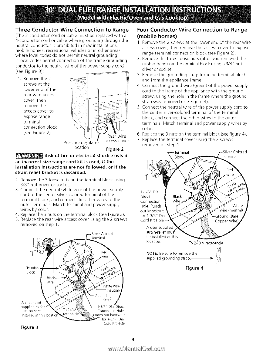
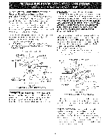
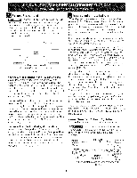
Three Conductor Wire Connection to Range (The 3-conductor cord or cable must be replaced with a 4-conductor cord or cable where grounding through the neutral conductor is prohibited in new installations, mobile homes, recreational vehicles or in other areas where local codes do not permit neutral grounding) If local codes permit connection of the frame grounding conductor to the neutral wire of the power supply cord (see Figure 3): 1. Remove the 2 screws at the lower end of the rear wire access cover, then remove the access cover to expose range terminal connection block (see Figure 2). Pressure regulator location Risk of fire an incorrect Installation strain relief or electrical shock Four Conductor (mobile homes) Wire Connection to Range Rear wire access cover Figure 2 exists if 1. Remove the 2 screws at the lower end of the rear wire access cover, then remove the access cover to expose range terminal connection block (see Figure 2). 2. Remove the three loose nuts (after you removed the rubber band) on the terminal block using a 3/8" nut driver or socket. 3. Remove the grounding strap from the terminal block and from the appliance frame. 4. Connect the ground wire (green) of the power supply cord to the frame of the appliance with the ground screw, using the hole in the frame where the ground strap was removed (see Figure 4). 5. Connect the neutral wire of the power supply cord to the center silver-colored terminal of the terminal block, and connect the other wires to the outer terminals. Match terminal and power supply wires by color. 6. Replace the 3 nuts on the terminal block (see figure 4). 7. Replace the terminal cover using the 2 screws removed on step 1. Terminal size range cord kit is used, if the Instructions are not followed, or if the bracket is discarded. 2. Remove the 3 loose nuts on the terminal block using 3/8" nut driver or socket. 3. Connect the neutral white wire of the power supply cord to the center silver-colored terminal of the terminal block, and connect the other wires to the outer terminals. Match terminal and power supply wires by color. 4. Replace the 3 nuts on the terminal block (see figure 3). 5. Replace the rear wire access cover using the 2 screws removed on step 1. Colored Terminal 1-1/8" Dia. Direct Connection Hole. Punch out knockout for 1-3/8" Dia. Cord Kit A user supplied strain-relief be installed at this location. NOTE: Be sure to remove To240 V receptacle the f_/ supplied grounding strap.. Terminal Block -_ Figure 4 ig A strainrelief supplied user must be installed at this Iocati( Strap 1-1/8" Dia. Direct Connection Hole. Punch out knockout for 1-3/8" Dia. Cord Kit Hole Figure 3 4
-
 1
1 -
 2
2 -
 3
3 -
 4
4 -
 5
5 -
 6
6 -
 7
7 -
 8
8 -
 9
9 -
 10
10 -
11
-
12
-
13
-
14
-
15
-
16
-
17
-
18
-
19
-
20
-
21
-
22
-
23
-
24
 |
 |