Kenwood 915DVD Instruction Manual - Page 50
Connection
 |
UPC - 019048146250
View all Kenwood 915DVD manuals
Add to My Manuals
Save this manual to your list of manuals |
Page 50 highlights
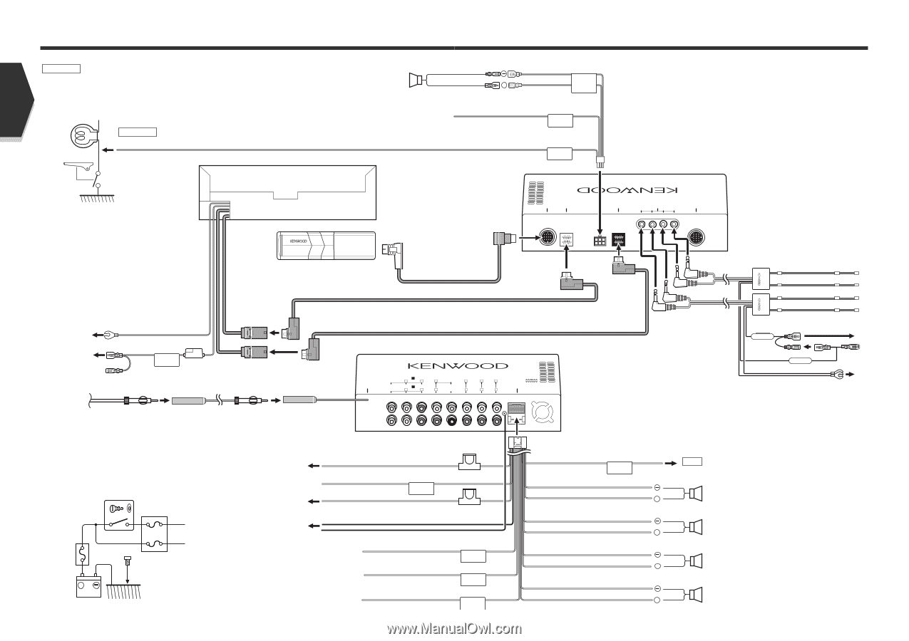
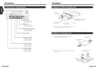
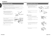
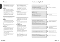
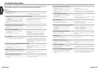
English Connection 2WARNING If you connect the ignition wire (red) and the battery wire (yellow) to the car chassis (ground), you may cause a short circuit, that in turn may start a fire. Always connect those wires to the power source running through the fuse box. Connect to the vehicle's parking brake detection switch harness using the supplied relay connector. 2CAUTION For the sake of safety, be sure to connect the parking sensor. Center Speaker To vehicle's reverse lamp harness Monitor unit (Black) + (Pink) (Black/White) CENTER REVERSE Parking sensor wire (Green) PRK SW Accessory 4 Receiver unit (rear side) TO MONITOR CENTER SP (BLACK) SENSOR LINE TO MONITOR TO 5L I/F (WHITE) TO NAVIGATION I/F TO TV ANTENNA Ground wire (Black) - (To car chassis) C Battery wire (Yellow) ( 5A ) B BATT Accessory 5 Disc Changer etc. Accessory 2 Cable (included in the disc changer) Accessory 3 Receiver unit (front side) FM/AM antenna input AV INPUT 1 VIDEO L R FM /AM ANTENNA AV INPUT 2 VIDEO L R AV OUTPUT L VIDEO SUB (MONO) L PREOUT REAR L FRONT L R CENTER R R R POWER Accessory ! ( 1A ) Ignition wire (Red) A ( 1A ) C Ground wire (Black) - (To car chassis) Ignition key switch Car fuse box (Main fuse) + Battery 98 English ACC A B Car fuse box C B To car light control switch A Battery wire (Yellow) Dimmer control wire (Orange/White) Ignition wire (Red) ILLUMI Ground wire (Black) - (To car chassis) C Depending on what antenna you are using, connect either to the control terminal of the motor antenna, or to the power terminal for the booster amplifier of the film-type antenna. When using the optional power amplifier, connect to its power control terminal. To "EXT.AMP.CONT." terminal of the amplifier having the external amp control function. Motor antenna control wire (Blue/White) Power control wire (Blue) External amplifier control wire (Pink/Black) ( 10A ) ( 3A ) ANT. CONT P CONT EXT.CONT Wiring harness (Accessory 1) TEL mute wire (Brown) MUTE White/Black + White Gray/Black + Gray Green/Black + Green Purple/Black + Purple Connect to the terminal that is grounded when either the telephone rings or during conversation. NOTE To connect the KENWOOD navigation system, consult your navigation manual. To front left speaker To front right speaker To rear left speaker To rear right speaker English 99
-
 1
1 -
2
-
3
-
4
-
5
-
6
-
7
-
8
-
9
-
10
-
11
-
12
-
13
-
14
-
15
-
16
-
17
-
18
-
19
-
20
-
21
-
22
-
23
-
24
-
25
-
26
-
27
-
28
-
29
-
30
-
31
-
32
-
33
-
34
-
35
-
36
-
37
-
38
-
39
-
40
-
41
-
42
-
43
-
44
-
 45
45 -
 46
46 -
 47
47 -
 48
48 -
 49
49 -
 50
50 -
 51
51 -
 52
52 -
 53
53 -
 54
54 -
 55
55 -
56
-
57
 |
 |