Kenwood 915DVD Instruction Manual - Page 51
Installation, Connection
 |
UPC - 019048146250
View all Kenwood 915DVD manuals
Add to My Manuals
Save this manual to your list of manuals |
Page 51 highlights
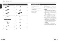
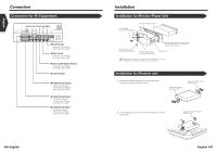
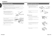
English Connection Connection for AV Equipments AV INPUT 1 VIDEO L R FM /AM ANTENNA AV INPUT 2 VIDEO L R AV OUTPUT L VIDEO SUB (MONO) L PREOUT REAR L FRONT L R CENTER R R R POWER ¶ Front Preout - Audio left output (White) - Audio right output (Red) ¶ Rear Preout - Audio left output (White) - Audio right output (Red) ¶ Sub-woofer (Mono) Preout - Audio left output (White) - Audio right output (Red) ¶ Center Preout ¶ Audio/Visual Output - Visual output (Yellow) - Audio left output (White) - Audio right output (Red) ¶ Audio/Visual input 2 - Visual input (Yellow) - Audio left input (White) - Audio right input (Red) ¶ Audio/Visual input 1 - Visual input (Yellow) - Audio left input (White) - Audio right input (Red) 100 English Installation Installation for Monitor/Player Unit Screw (M4X8) (commercially available) Firewall or metal support Self-tapping screw (commercially available) Bend the tabs of the mounting sleeve with a screwdriver or similar utensil and attach it in place. Metal mounting strap (commercially available) Accessory 6 Make sure that the unit is installed securely in place. If the unit is unstable, it may malfunction (eg, the sound may skip). Installation for Receiver unit 1. Attach the installation brackets 0 to the sides of the hideaway unit using the sems bolts 8. Installation brackets (Accessory 0) Sems bolts (M4 × 8 mm) (Accessory 8) 2. Use the tapping screw 9 to secure the hideaway unit to the audio board. Tapping screw (ø4 × 16 mm) (Accessory 9) ;;;;;;;;;;;; English 101
-
 1
1 -
2
-
3
-
4
-
5
-
6
-
7
-
8
-
9
-
10
-
11
-
12
-
13
-
14
-
15
-
16
-
17
-
18
-
19
-
20
-
21
-
22
-
23
-
24
-
25
-
26
-
27
-
28
-
29
-
30
-
31
-
32
-
33
-
34
-
35
-
36
-
37
-
38
-
39
-
40
-
41
-
42
-
43
-
44
-
45
-
 46
46 -
 47
47 -
 48
48 -
 49
49 -
 50
50 -
 51
51 -
 52
52 -
 53
53 -
 54
54 -
 55
55 -
 56
56 -
57
 |
 |
