Konica Minolta magicolor 1690MF Service Manual - Page 52
Outline, Laser exposure process
 |
View all Konica Minolta magicolor 1690MF manuals
Add to My Manuals
Save this manual to your list of manuals |
Page 52 highlights
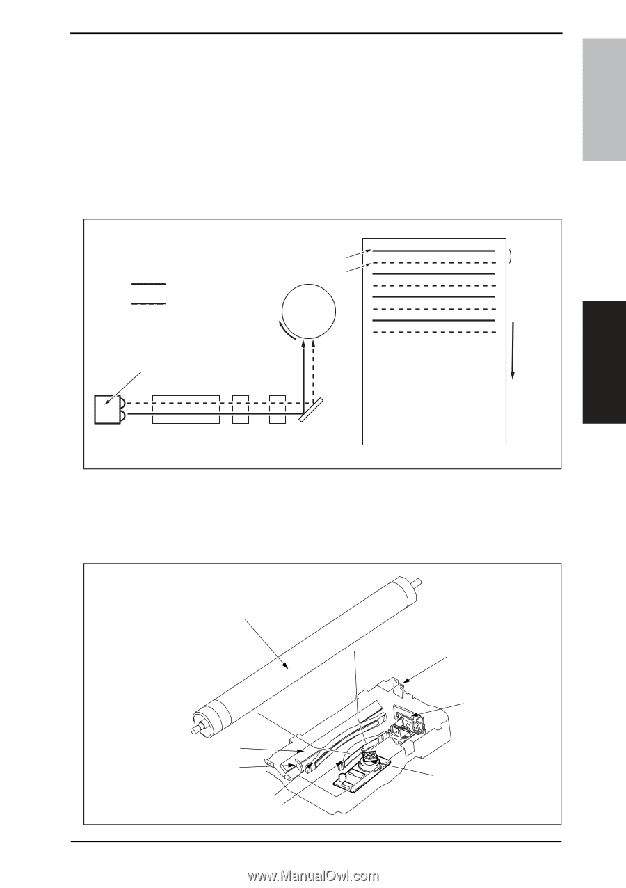
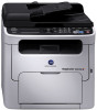
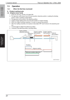
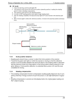
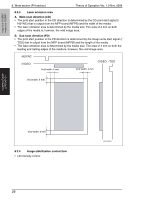
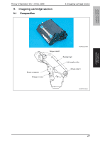
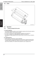
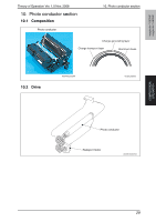
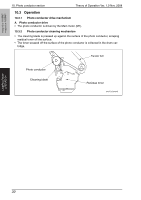
magicolor 1680MF magicolor 1690MF Theory of Operation Ver. 1.0 Nov. 2008 8. Write section (PH section) 8.2 Operation 8.2.1 Outline • The surface of the photo conductor is irradiated with a laser light and an electrostatic latent image is thereby formed. • The polygon mirror has four faces. The machine uses a two-beam array LD to inhibit the speed of the polygon mirror from increasing because of the decreased number of faces the polygon mirror has as compared with the conventional models. • The two-beam array LD consists of two LD elements arranged vertically. Two lines are scanned with two laser beams emitted from these two LD elements through a single face of the polygon mirror. Photo conductor surface Two lines are scanned in a single scan motion. Beam A Beam B Direction of rotation of photo conductor Beam A Beam B Photo conductor Laser diode G1 lens G2 lens Direction of rotation of photo conductor Polygon mirror Return mirror A034T2E582AA 8.2.2 Laser exposure process 1. The laser light emitted from the Semiconductor laser strikes the polygon mirror. 2. The polygon mirror with four faces is rotated at high speeds by the polygon motor. 3. The SOS sensor ensures that the laser light emission start timing remains constant for each line of main scan. COMPOSITION/ OPERATION Photo conductor Return mirror SOS mirror G2 Lens G1 Lens SOS sensor Semiconductor laser Polygon mirror A034T2C505AA 25
-
 1
1 -
2
-
3
-
4
-
5
-
6
-
7
-
8
-
9
-
10
-
11
-
12
-
13
-
14
-
15
-
16
-
17
-
18
-
19
-
20
-
21
-
22
-
23
-
24
-
25
-
26
-
27
-
28
-
29
-
30
-
31
-
32
-
33
-
34
-
35
-
36
-
37
-
38
-
39
-
40
-
41
-
42
-
43
-
44
-
45
-
46
-
 47
47 -
 48
48 -
 49
49 -
 50
50 -
 51
51 -
 52
52 -
 53
53 -
 54
54 -
 55
55 -
 56
56 -
 57
57 -
58
-
59
-
60
-
61
-
62
-
63
-
64
-
65
-
66
-
67
-
68
-
69
-
70
-
71
-
72
-
73
-
74
-
75
-
76
-
77
-
78
-
79
-
80
-
81
-
82
-
83
-
84
-
85
-
86
-
87
-
88
-
89
-
90
-
91
-
92
-
93
-
94
-
95
-
96
-
97
-
98
-
99
-
100
-
101
-
102
-
103
-
104
-
105
-
106
-
107
-
108
-
109
-
110
-
111
-
112
-
113
-
114
-
115
-
116
-
117
-
118
-
119
-
120
-
121
-
122
-
123
-
124
-
125
-
126
-
127
-
128
-
129
-
130
-
131
-
132
-
133
-
134
-
135
-
136
-
137
-
138
-
139
-
140
-
141
-
142
-
143
-
144
 |
 |