Konica Minolta magicolor 1690MF Service Manual - Page 76
ATVC Auto transfer voltage control, Overview of ATVC operation, 1st transfer ATVC operation, 2nd - how to change toner
 |
View all Konica Minolta magicolor 1690MF manuals
Add to My Manuals
Save this manual to your list of manuals |
Page 76 highlights
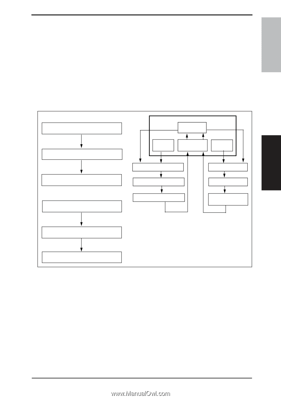
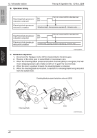
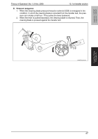
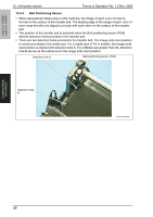
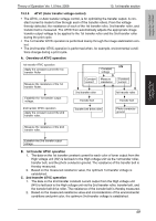
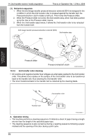
magicolor 1680MF magicolor 1690MF COMPOSITION/ OPERATION Theory of Operation Ver. 1.0 Nov. 2008 13. 1st transfer section 13.3.5 ATVC (Auto transfer voltage control) • The ATVC, or Auto transfer voltage control, is for optimizing the transfer output. A constant current is made to flow through each of the transfer rollers. From the voltage thereby detected, the resistance of each of the 1st transfer roller, 2nd transfer roller, and transfer belt is measured. The ATVC then automatically adjusts the appropriate image transfer output voltage to be applied to the 1st transfer roller and the 2nd transfer roller during the print cycle. • The 1st transfer ATVC operation is performed mainly through the image stabilization control. • The 2nd transfer ATVC operation is performed when, for example, environmental conditions change during a print cycle. A. Overview of ATVC operation 1st transfer ATVC operation Apply the constant current the 1st transfer Roller HV Constant voltage Measure the resistance of the 1st transfer Roller. Establish the 1st transfer output voltage. Constant Measure current resistance Constant current 2nd transfer roller Transfer belt 1st transfer roller Transfer belt 2nd transfer ATVC operation Apply the constant current the 2nd transfer roller. Transfer belt drive roller Photo conductor ground Measure the resistance of the 2nd transfer roller. Establish the 2nd transfer output voltage. B. 1st transfer ATVC operation 1. The data on the 1st transfer constant current for each color of toner output from the High voltage unit (HV) is fed back to the High voltage unit via the 1st transfer roller, transfer belt, and the photo conductor ground. The resistance of the transfer belt is thereby measured. 2. Based on the measured resistance value, the optimum 1st transfer voltage is established. C. 2nd transfer ATVC operation 1. The data on the 2nd transfer constant current output from the High voltage unit (HV) is fed back to the High voltage unit via the 2nd transfer roller, transfer belt, and the transfer belt drive roller. The resistance of the transfer belt is thereby measured. 2. Based on the measured resistance value and inconsideration of the environmental conditions and print color, the optimum 2nd transfer voltage is established. 49
-
 1
1 -
2
-
3
-
4
-
5
-
6
-
7
-
8
-
9
-
10
-
11
-
12
-
13
-
14
-
15
-
16
-
17
-
18
-
19
-
20
-
21
-
22
-
23
-
24
-
25
-
26
-
27
-
28
-
29
-
30
-
31
-
32
-
33
-
34
-
35
-
36
-
37
-
38
-
39
-
40
-
41
-
42
-
43
-
44
-
45
-
46
-
47
-
48
-
49
-
50
-
51
-
52
-
53
-
54
-
55
-
56
-
57
-
58
-
59
-
60
-
61
-
62
-
63
-
64
-
65
-
66
-
67
-
68
-
69
-
70
-
 71
71 -
 72
72 -
 73
73 -
 74
74 -
 75
75 -
 76
76 -
 77
77 -
 78
78 -
 79
79 -
 80
80 -
 81
81 -
82
-
83
-
84
-
85
-
86
-
87
-
88
-
89
-
90
-
91
-
92
-
93
-
94
-
95
-
96
-
97
-
98
-
99
-
100
-
101
-
102
-
103
-
104
-
105
-
106
-
107
-
108
-
109
-
110
-
111
-
112
-
113
-
114
-
115
-
116
-
117
-
118
-
119
-
120
-
121
-
122
-
123
-
124
-
125
-
126
-
127
-
128
-
129
-
130
-
131
-
132
-
133
-
134
-
135
-
136
-
137
-
138
-
139
-
140
-
141
-
142
-
143
-
144
 |
 |