LG KU580 Service Manual - Page 42
E. Camera Data Interface CDI Block
 |
View all LG KU580 manuals
Add to My Manuals
Save this manual to your list of manuals |
Page 42 highlights
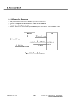
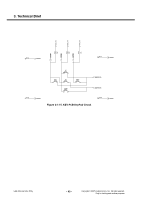
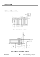
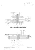
3. Technical Brief E. Camera Data Interface (CDI) Block The camera data interface (CDI) block is designed to support a range of still image camera modules. An 8-bit parallel bus supports data transfer from the camera module to the CDI. The pixel clock is an output clock from the camera module to the CDI and qualifies the data on the parallel bus. One byte of data is captured on each rising edge of the pixel clock. CDI allows the pixel clock to be in the range of 100 kHz to 16 MHz. The horizontal synchronization line is an input from the camera module and defines one scanline of image data. The horizontal synchronization line can be programmed to be active high or low. The vertical synchronization line is an input from the camera module and defines one image frame (image height) of data. The vertical synchronization line can be programmed to be active high or low. The frame rate can be adjusted by skipping frames and various interrupts are used to inform the application CPU regarding the progress of incoming images and potential errors. The normal data format on the data bus is YUV 4:2:2 (raw binary image data) according to the CCIR-656 standard. A function within the CDI can be programmed to reorder the YUV parameters as they pass through the CDI. In addition, the CDI is able to detect the end of an image and perform some truncation as well as overflow conditions. There is nothing preventing the use of other data types such as JPEG or RGB (as long as the timing is followed), but only YUV data can be sent to the display. Camera images can also be sent to a DMA channel to store the image in external memory. The I2C interface and GPIO are part of the interface to the camera module, but they are not part of the CDI block. The I2C is used to set-up and control the camera module. The camera module I2C lines must go high impedance when the supply is removed from the camera. The I2C commands needed to control the camera, as well as the functional behavior of the module, are also different for each implementation. The ON-signal (GPIO) is used to power-on the camera from Standby or Off mode (implementation dependent). This signal must be held low when the mobile equipment is powered down and during the mobile equipment reset period. The GPIO pin can also be an input or high impedance during mobile equipment reset and start. In this case, it must have pull-down to ground. The camera module reset signal is an output to the camera module. Copyright © 2007 LG Electronics. Inc. All right reserved. Only for training and service purposes - 43 - LGE Internal Use Only
-
 1
1 -
2
-
3
-
4
-
5
-
6
-
7
-
8
-
9
-
10
-
11
-
12
-
13
-
14
-
15
-
16
-
17
-
18
-
19
-
20
-
21
-
22
-
23
-
24
-
25
-
26
-
27
-
28
-
29
-
30
-
31
-
32
-
33
-
34
-
35
-
36
-
 37
37 -
 38
38 -
 39
39 -
 40
40 -
 41
41 -
 42
42 -
 43
43 -
 44
44 -
 45
45 -
 46
46 -
 47
47 -
48
-
49
-
50
-
51
-
52
-
53
-
54
-
55
-
56
-
57
-
58
-
59
-
60
-
61
-
62
-
63
-
64
-
65
-
66
-
67
-
68
-
69
-
70
-
71
-
72
-
73
-
74
-
75
-
76
-
77
-
78
-
79
-
80
-
81
-
82
-
83
-
84
-
85
-
86
-
87
-
88
-
89
-
90
-
91
-
92
-
93
-
94
-
95
-
96
-
97
-
98
-
99
-
100
-
101
-
102
-
103
-
104
-
105
-
106
-
107
-
108
-
109
-
110
-
111
-
112
-
113
-
114
-
115
-
116
-
117
-
118
-
119
-
120
-
121
-
122
-
123
-
124
-
125
-
126
-
127
-
128
-
129
-
130
-
131
-
132
-
133
-
134
-
135
-
136
-
137
-
138
-
139
-
140
-
141
-
142
-
143
-
144
-
145
-
146
-
147
-
148
-
149
-
150
-
151
-
152
-
153
-
154
-
155
-
156
-
157
-
158
-
159
-
160
-
161
-
162
-
163
-
164
-
165
-
166
-
167
-
168
-
169
-
170
-
171
-
172
-
173
-
174
-
175
-
176
-
177
-
178
-
179
-
180
-
181
-
182
-
183
-
184
-
185
-
186
-
187
-
188
-
189
-
190
-
191
-
192
-
193
-
194
-
195
-
196
-
197
-
198
-
199
-
200
-
201
-
202
-
203
-
204
-
205
-
206
-
207
-
208
-
209
 |
 |
