LG KU580 Service Manual - Page 54
B. Voice Call Uplink Mode Receiver,Speaker,Headset
 |
View all LG KU580 manuals
Add to My Manuals
Save this manual to your list of manuals |
Page 54 highlights
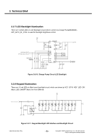
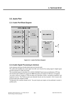
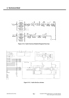
3. Technical Brief B. Voice Call Uplink Mode (Receiver,Speaker,Headset) This section provides a detailed description of the Voice Call TX functions. Figure 3-3-5. Voice call Uplink Scheme From the audio path view point, voice call has the same structure as video telephony. The TXMIXconnection enables insertion of audio into the uplink audio path. This can, for example, be used to play dictation recordings for the listener at the other party, in a voice call or video telephony call. The connection to TXMIX from the Audio Mixer must be performed in 8 kHz mono, since this is supported by the Voice mode. Due to performance reasons it may not be possible to decode every audio format during video telephony. Each Voice Uplink Mode paths shown below. Receiver Mode : C-MIC(SP0102BE3) → Veronica Input(MIC1N/1P) Loud Speaker Mode : C-MIC(SP0102BE3) → Veronica Input(MIC1N/1P) Video Telephony Mode : C-MIC(SP0102BE3) → Veronica Input(MIC1N/1P) Headset Mode : Headset MIC → Veronica Input(AUXI1N/1P) When the headset is inserted, EAR_DETECT_n(Circuit Diagram net Name) converted into low state So, the headset icon is displayed on Main LCD. Copyright © 2007 LG Electronics. Inc. All right reserved. Only for training and service purposes - 55 - LGE Internal Use Only
-
 1
1 -
2
-
3
-
4
-
5
-
6
-
7
-
8
-
9
-
10
-
11
-
12
-
13
-
14
-
15
-
16
-
17
-
18
-
19
-
20
-
21
-
22
-
23
-
24
-
25
-
26
-
27
-
28
-
29
-
30
-
31
-
32
-
33
-
34
-
35
-
36
-
37
-
38
-
39
-
40
-
41
-
42
-
43
-
44
-
45
-
46
-
47
-
48
-
 49
49 -
 50
50 -
 51
51 -
 52
52 -
 53
53 -
 54
54 -
 55
55 -
 56
56 -
 57
57 -
 58
58 -
 59
59 -
60
-
61
-
62
-
63
-
64
-
65
-
66
-
67
-
68
-
69
-
70
-
71
-
72
-
73
-
74
-
75
-
76
-
77
-
78
-
79
-
80
-
81
-
82
-
83
-
84
-
85
-
86
-
87
-
88
-
89
-
90
-
91
-
92
-
93
-
94
-
95
-
96
-
97
-
98
-
99
-
100
-
101
-
102
-
103
-
104
-
105
-
106
-
107
-
108
-
109
-
110
-
111
-
112
-
113
-
114
-
115
-
116
-
117
-
118
-
119
-
120
-
121
-
122
-
123
-
124
-
125
-
126
-
127
-
128
-
129
-
130
-
131
-
132
-
133
-
134
-
135
-
136
-
137
-
138
-
139
-
140
-
141
-
142
-
143
-
144
-
145
-
146
-
147
-
148
-
149
-
150
-
151
-
152
-
153
-
154
-
155
-
156
-
157
-
158
-
159
-
160
-
161
-
162
-
163
-
164
-
165
-
166
-
167
-
168
-
169
-
170
-
171
-
172
-
173
-
174
-
175
-
176
-
177
-
178
-
179
-
180
-
181
-
182
-
183
-
184
-
185
-
186
-
187
-
188
-
189
-
190
-
191
-
192
-
193
-
194
-
195
-
196
-
197
-
198
-
199
-
200
-
201
-
202
-
203
-
204
-
205
-
206
-
207
-
208
-
209
 |
 |
