LG KU580 Service Manual - Page 69
C. Synthesizer
 |
View all LG KU580 manuals
Add to My Manuals
Save this manual to your list of manuals |
Page 69 highlights
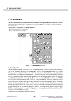
3. Technical Brief C. Synthesizer The RX and TX RF VCOs are fully integrated and self-calibrated on manufacturing tolerances. They have 16 different frequency ranges that are selected internally depending on the frequency programming. The calibration is done on each low to high logical transition of the SYNON bit in the control register or on each change of the integer divider ratio of the RF fractional N synthesizer. A high-performance RF fractional-N synthesizer PLL is included on-chip which enables the frequency of the RF VCO to be synthesized. The frequency is set through the 3-wire serial programming bus. The PLL is based on Sigma-Delta (∑) fractional-N synthesis that enables the required channel frequency, including Automatic Frequency Control (AFC) from a free running external 26 MHz reference frequency. Very low close-in-phase noise is achieved. This allows widening of the PLL loop bandwidth and shorter settling time. The programmable main dividers are controlled by a second order ∑-modulus controller. They divide the RF VCO signals down to frequencies of 26 MHz (12 Hz step programmability). Their phase is then compared in a digital Phase/Frequency Detector (PFD) to the 26 MHz reference clock signal. The phase error information is fed back to the RF VCO through the charge pump circuit that .sources. into or .sinks. current from the loop filter capacitor, thus changing the VCO frequency such that the loop finally gets phase-locked. WTXMOD_BAND_I R118 0 R119 52 G2 G1 OUT IN 4 G3 1 0 SAFEB1G95KA0F00 3 FL102 L105 NA R120 0 C122 NA C123 NA VRADA_2V75 C126 NA WTX_I_P WTX_I_N WTX_Q_P WTX_Q_N VRADA_2V75 WPA_BIAS WPA_VCC C120 NA FL100 R117 0 SAFEB2G14FA0F00 45 O2 G2 IN O1 G1 1 32 L106 5.6nH C125 NA C124 NA 41 PGND 40 VCCTX 39 RF_DAC2 38 RF_DAC1 37 NC13 36 MIX1_B 35 MIX1_A 34 NC12 33 NC11 32 NC10 31 VCCRX 1 30 GNDTX NC9 2 29 NC1 LNA1_OUT 3 28 NC2 NC8 4 TX_1 5 U104 27 LNA1_IN 26 NC3 NC7 6 25 VCCLOTX NC6 7 24 TXIA VCCLORX 8 TXIB RF3100_OM6195HN NC5 23 9 22 TXQA VDD 10 21 TXQB TST VRADA_2V75 VDIGRAD_1V8 VRADA_2V75 C130 NA C127 5.6p C131 NA R121 0 L107 4.7nH 11 VGACTL 12 DATA 13 CLK 14 EN 15 REFIN 16 NC4 17 RXIA 18 RXIB 19 RXQA 20 RXQB RF_CTRL_DATA RF_CTRL_CLK RF_CTRL_STRB WCLK C133 8.2p R124 200 R127 200 R128 200 R129 200 WRX_Q_N WRX_Q_P WRX_I_N WRX_I_P Figure 3-7-4. WCDMA Transceiver schematic WRX_BAND_I LGE Internal Use Only - 70 - Copyright © 2007 LG Electronics. Inc. All right reserved. Only for training and service purposes
-
 1
1 -
2
-
3
-
4
-
5
-
6
-
7
-
8
-
9
-
10
-
11
-
12
-
13
-
14
-
15
-
16
-
17
-
18
-
19
-
20
-
21
-
22
-
23
-
24
-
25
-
26
-
27
-
28
-
29
-
30
-
31
-
32
-
33
-
34
-
35
-
36
-
37
-
38
-
39
-
40
-
41
-
42
-
43
-
44
-
45
-
46
-
47
-
48
-
49
-
50
-
51
-
52
-
53
-
54
-
55
-
56
-
57
-
58
-
59
-
60
-
61
-
62
-
63
-
 64
64 -
 65
65 -
 66
66 -
 67
67 -
 68
68 -
 69
69 -
 70
70 -
 71
71 -
 72
72 -
 73
73 -
 74
74 -
75
-
76
-
77
-
78
-
79
-
80
-
81
-
82
-
83
-
84
-
85
-
86
-
87
-
88
-
89
-
90
-
91
-
92
-
93
-
94
-
95
-
96
-
97
-
98
-
99
-
100
-
101
-
102
-
103
-
104
-
105
-
106
-
107
-
108
-
109
-
110
-
111
-
112
-
113
-
114
-
115
-
116
-
117
-
118
-
119
-
120
-
121
-
122
-
123
-
124
-
125
-
126
-
127
-
128
-
129
-
130
-
131
-
132
-
133
-
134
-
135
-
136
-
137
-
138
-
139
-
140
-
141
-
142
-
143
-
144
-
145
-
146
-
147
-
148
-
149
-
150
-
151
-
152
-
153
-
154
-
155
-
156
-
157
-
158
-
159
-
160
-
161
-
162
-
163
-
164
-
165
-
166
-
167
-
168
-
169
-
170
-
171
-
172
-
173
-
174
-
175
-
176
-
177
-
178
-
179
-
180
-
181
-
182
-
183
-
184
-
185
-
186
-
187
-
188
-
189
-
190
-
191
-
192
-
193
-
194
-
195
-
196
-
197
-
198
-
199
-
200
-
201
-
202
-
203
-
204
-
205
-
206
-
207
-
208
-
209
 |
 |
