LG KU580 Service Manual - Page 67
WCDMA Part
 |
View all LG KU580 manuals
Add to My Manuals
Save this manual to your list of manuals |
Page 67 highlights
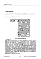
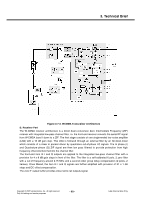
3. Technical Brief 3.7.2. WCDMA Part The W-CDMA transceiver uses differential analog in-phase and quadrature-phase interfaces, that is an IQ-interface, both in the receiver and transmitter information path. The transceiver has the following general features: • Power class : Power class 3 (+24dBm) in Band I • Zero-IF Receiver.No IF filter needed • Direct IQ modulation transmitter Figure 3-7-2. WCDMA RF structure A. Transmitter Part The W-CDMA transmitter architecture is an on frequency linear direct up-conversion IQ-modulator. The TX IQ modulator has differential voltage I and Q inputs. It converts input signals to RF output frequency and is designed to achieve LO and image suppression. The in-phase and quadraturephase reconstruction filters are fully integrated and a programmable gain amplifier implements the gain control. The transmit output stage provides at least +5 dBm at maximum power control at the singleended 50 Ω output. Gain is set through the 3-wire bus. An external SAW filter between the WCDMA circuit and the power amplifier is used to improve noise performance. Two 10-bit DACs are used to control the DC/DC converter and the PA gain. After the power amplifier, the signal is sent through an isolator and through the duplex filter, which directs the transmit signal to the antenna connector through the antenna switch. The supply voltage and bias of the power amplifier are adapted depending on the output power to achieve high efficiency at every transmitter power level. A high efficiency DC/DC converter regulates the supply voltage and the bias operation point is controlled by a D/Aconverter in the W-CDMA radio circuit. These DACs are controlled through the 3-wire-bus LGE Internal Use Only - 68 - Copyright © 2007 LG Electronics. Inc. All right reserved. Only for training and service purposes
-
 1
1 -
2
-
3
-
4
-
5
-
6
-
7
-
8
-
9
-
10
-
11
-
12
-
13
-
14
-
15
-
16
-
17
-
18
-
19
-
20
-
21
-
22
-
23
-
24
-
25
-
26
-
27
-
28
-
29
-
30
-
31
-
32
-
33
-
34
-
35
-
36
-
37
-
38
-
39
-
40
-
41
-
42
-
43
-
44
-
45
-
46
-
47
-
48
-
49
-
50
-
51
-
52
-
53
-
54
-
55
-
56
-
57
-
58
-
59
-
60
-
61
-
 62
62 -
 63
63 -
 64
64 -
 65
65 -
 66
66 -
 67
67 -
 68
68 -
 69
69 -
 70
70 -
 71
71 -
 72
72 -
73
-
74
-
75
-
76
-
77
-
78
-
79
-
80
-
81
-
82
-
83
-
84
-
85
-
86
-
87
-
88
-
89
-
90
-
91
-
92
-
93
-
94
-
95
-
96
-
97
-
98
-
99
-
100
-
101
-
102
-
103
-
104
-
105
-
106
-
107
-
108
-
109
-
110
-
111
-
112
-
113
-
114
-
115
-
116
-
117
-
118
-
119
-
120
-
121
-
122
-
123
-
124
-
125
-
126
-
127
-
128
-
129
-
130
-
131
-
132
-
133
-
134
-
135
-
136
-
137
-
138
-
139
-
140
-
141
-
142
-
143
-
144
-
145
-
146
-
147
-
148
-
149
-
150
-
151
-
152
-
153
-
154
-
155
-
156
-
157
-
158
-
159
-
160
-
161
-
162
-
163
-
164
-
165
-
166
-
167
-
168
-
169
-
170
-
171
-
172
-
173
-
174
-
175
-
176
-
177
-
178
-
179
-
180
-
181
-
182
-
183
-
184
-
185
-
186
-
187
-
188
-
189
-
190
-
191
-
192
-
193
-
194
-
195
-
196
-
197
-
198
-
199
-
200
-
201
-
202
-
203
-
204
-
205
-
206
-
207
-
208
-
209
 |
 |
