Lenovo M5800 Lenovo M5800 Hardware Maintenance Manual - Page 72
Locating internal drives
 |
View all Lenovo M5800 manuals
Add to My Manuals
Save this manual to your list of manuals |
Page 72 highlights
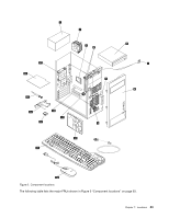
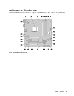
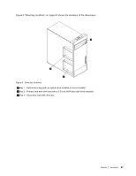
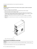
1 4-pin power connector 2 Microprocessor 3 Microprocessor fan connector 4 Memory slot 1 (DIMM 1) 5 Memory slot 2 (DIMM 2) 6 Memory slot 3 (DIMM 3) 7 Memory slot 4 (DIMM 4) 8 Thermal sensor connector 9 4-pin power connectors (2) 10 14-pin power connector 11 Battery 12 SATA 3.0 connectors (4) 13 Power fan connector 14 Parallel connector 15 Front panel connector (for connecting LED indicators and the power switch) 16 Front USB connector 1 (for connecting USB ports 1 and 2 on the front bezel) 17 Front USB connector 2 (for connecting additional USB devices) 18 Clear CMOS (Complementary Metal Oxide Semiconductor)/Recovery jumper 19 Serial (COM2) connector 20 Internal speaker connector 21 Front audio connector 22 PCI card slots (2) 23 PCI Express x1 card slot 24 PCI Express x16 graphics card slot 25 Cover presence switch connector (Intrusion switch connector) 26 System fan connector 27 PS/2 keyboard and mouse connector Locating internal drives Internal drives are devices that your computer uses to read and store data. You can add drives to your computer to increase storage capacity and enable your computer to read other types of media. Internal drives are installed in bays. In this manual, the bays are referred to as bay 1, bay 2, and so on. When installing or replacing an internal drive, it is important to note the type and size of the drive that you can install or replace in each bay and correctly connect the cables to the drive installed. Refer to the appropriate section in "Installing or replacing hardware" on page 69 for instructions on how to install or replace internal drives for your computer. 66 Lenovo M5800 Hardware Maintenance Manual
-
 1
1 -
2
-
3
-
4
-
5
-
6
-
7
-
8
-
9
-
10
-
11
-
12
-
13
-
14
-
15
-
16
-
17
-
18
-
19
-
20
-
21
-
22
-
23
-
24
-
25
-
26
-
27
-
28
-
29
-
30
-
31
-
32
-
33
-
34
-
35
-
36
-
37
-
38
-
39
-
40
-
41
-
42
-
43
-
44
-
45
-
46
-
47
-
48
-
49
-
50
-
51
-
52
-
53
-
54
-
55
-
56
-
57
-
58
-
59
-
60
-
61
-
62
-
63
-
64
-
65
-
66
-
 67
67 -
 68
68 -
 69
69 -
 70
70 -
 71
71 -
 72
72 -
 73
73 -
 74
74 -
 75
75 -
 76
76 -
 77
77 -
78
-
79
-
80
-
81
-
82
-
83
-
84
-
85
-
86
-
87
-
88
-
89
-
90
-
91
-
92
-
93
-
94
-
95
-
96
-
97
-
98
-
99
-
100
-
101
-
102
-
103
-
104
-
105
-
106
-
107
-
108
-
109
-
110
-
111
-
112
-
113
-
114
-
115
-
116
-
117
-
118
-
119
-
120
 |
 |