Lenovo M5800 Lenovo M5800 Hardware Maintenance Manual - Page 81
Installing or replacing a memory module, UDIMMs in any combination up to a maximum of 32 GB.
 |
View all Lenovo M5800 manuals
Add to My Manuals
Save this manual to your list of manuals |
Page 81 highlights
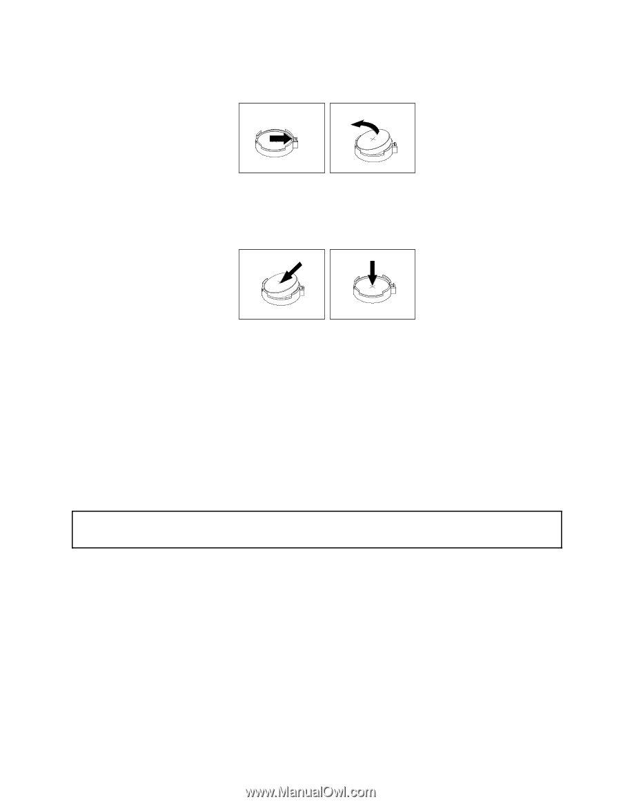
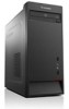
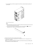
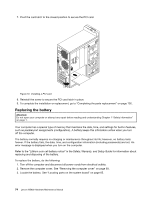
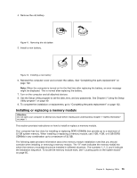
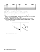
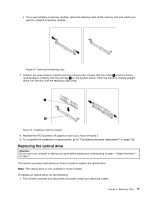
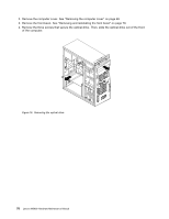
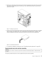
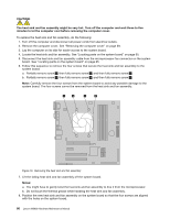
4. Remove the old battery. Figure 11. Removing the old battery 5. Install a new battery. Figure 12. Installing a new battery 6. Reinstall the computer cover and connect the cables. See "Completing the parts replacement" on page 102. Note: When the computer is turned on for the first time after replacing the battery, an error message might be displayed. This is normal after replacing the battery. 7. Turn on the computer and all attached devices. 8. Use the Setup Utility program to set the date, time, and any passwords. See Chapter 5 "Using the Setup Utility program" on page 49. 9. To complete the installation or replacement, go to "Completing the parts replacement" on page 102. Installing or replacing a memory module Attention: Do not open your computer or attempt any repair before reading and understanding Chapter 1 "Safety information" on page 1. This section provides instructions on how to install or replace a memory module. Your computer has four slots for installing or replacing DDR3 UDIMMs that provide up to a maximum of 32 GB system memory. When installing or replacing a memory module, use 2 GB, 4 GB, or 8 GB DDR3 UDIMMs in any combination up to a maximum of 32 GB. The following table provides information about the memory module installation rules that you should consider when installing or removing a memory module. The "X" mark indicates the memory slot(s) into which the memory module(s) should be installed in different situations. The numbers 1, 2, 3, and 4 indicate the installation sequence. To locate the memory module slots, see "Locating parts on the system board" on page 65. Chapter 8. Replacing FRUs 75
-
 1
1 -
2
-
3
-
4
-
5
-
6
-
7
-
8
-
9
-
10
-
11
-
12
-
13
-
14
-
15
-
16
-
17
-
18
-
19
-
20
-
21
-
22
-
23
-
24
-
25
-
26
-
27
-
28
-
29
-
30
-
31
-
32
-
33
-
34
-
35
-
36
-
37
-
38
-
39
-
40
-
41
-
42
-
43
-
44
-
45
-
46
-
47
-
48
-
49
-
50
-
51
-
52
-
53
-
54
-
55
-
56
-
57
-
58
-
59
-
60
-
61
-
62
-
63
-
64
-
65
-
66
-
67
-
68
-
69
-
70
-
71
-
72
-
73
-
74
-
75
-
 76
76 -
 77
77 -
 78
78 -
 79
79 -
 80
80 -
 81
81 -
 82
82 -
 83
83 -
 84
84 -
 85
85 -
 86
86 -
87
-
88
-
89
-
90
-
91
-
92
-
93
-
94
-
95
-
96
-
97
-
98
-
99
-
100
-
101
-
102
-
103
-
104
-
105
-
106
-
107
-
108
-
109
-
110
-
111
-
112
-
113
-
114
-
115
-
116
-
117
-
118
-
119
-
120
 |
 |