Lenovo M5800 Lenovo M5800 Hardware Maintenance Manual - Page 85
Replacing the heat sink and fan assembly
 |
View all Lenovo M5800 manuals
Add to My Manuals
Save this manual to your list of manuals |
Page 85 highlights
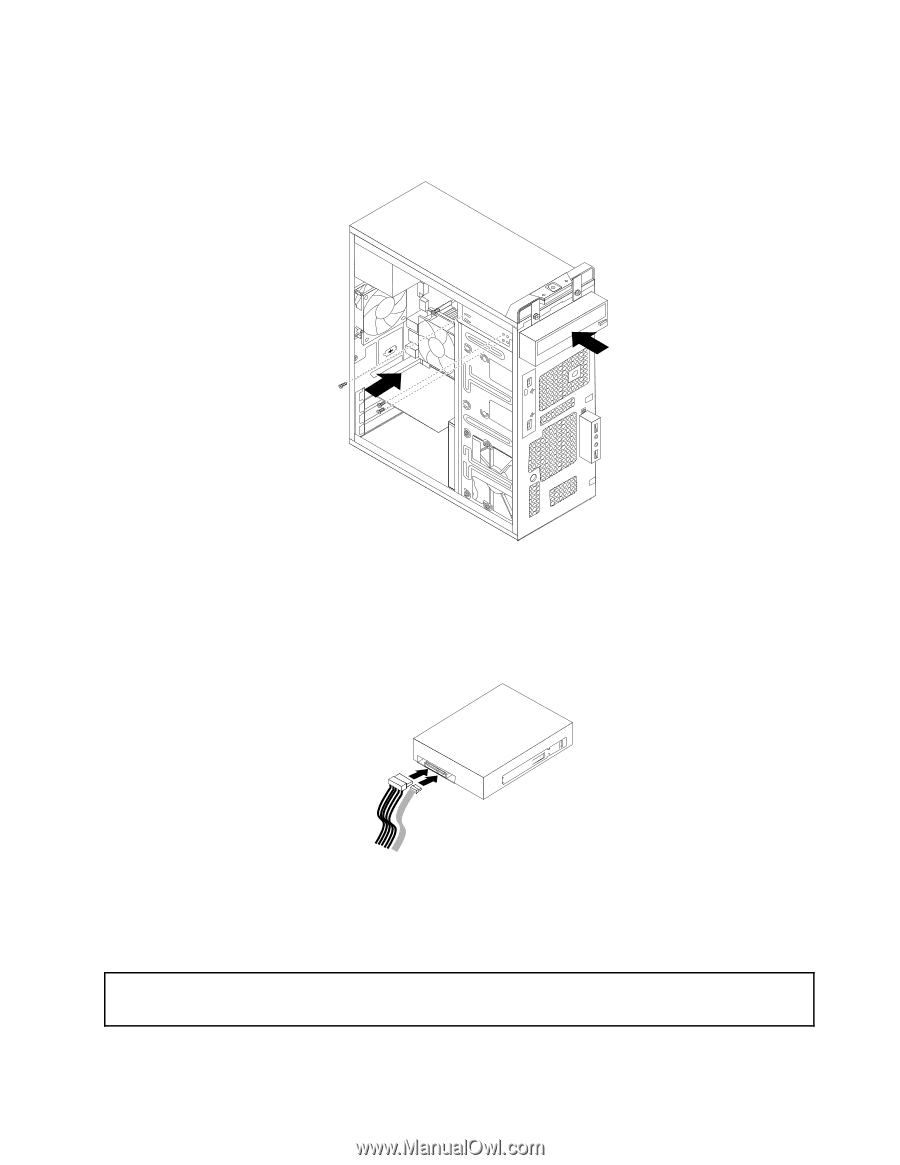
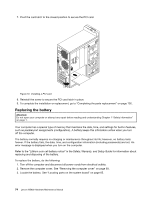
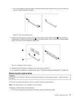
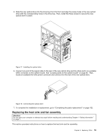
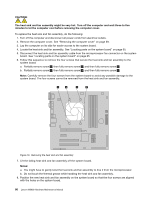
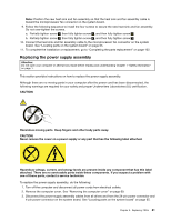
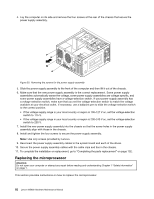
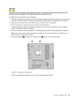
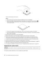
5. Slide the new optical drive into the drive bay from the front and align the screw holes in the new optical drive with the corresponding holes in the drive bay. Then, install the three screws to secure the new optical drive in place. Figure 17. Installing the optical drive 6. Connect one end of the signal cable to the rear of the new optical drive and the other end to an available SATA connector on the system board. See "Locating parts on the system board" on page 65. Then, locate an available five-wire power connector and connect it to the rear of the new optical drive. Figure 18. Connecting the optical drive 7. To complete the installation or replacement, go to "Completing the parts replacement" on page 102. Replacing the heat sink and fan assembly Attention: Do not open your computer or attempt any repair before reading and understanding Chapter 1 "Safety information" on page 1. This section provides instructions on how to replace the heat sink and fan assembly. Chapter 8. Replacing FRUs 79
-
 1
1 -
2
-
3
-
4
-
5
-
6
-
7
-
8
-
9
-
10
-
11
-
12
-
13
-
14
-
15
-
16
-
17
-
18
-
19
-
20
-
21
-
22
-
23
-
24
-
25
-
26
-
27
-
28
-
29
-
30
-
31
-
32
-
33
-
34
-
35
-
36
-
37
-
38
-
39
-
40
-
41
-
42
-
43
-
44
-
45
-
46
-
47
-
48
-
49
-
50
-
51
-
52
-
53
-
54
-
55
-
56
-
57
-
58
-
59
-
60
-
61
-
62
-
63
-
64
-
65
-
66
-
67
-
68
-
69
-
70
-
71
-
72
-
73
-
74
-
75
-
76
-
77
-
78
-
79
-
 80
80 -
 81
81 -
 82
82 -
 83
83 -
 84
84 -
 85
85 -
 86
86 -
 87
87 -
 88
88 -
 89
89 -
 90
90 -
91
-
92
-
93
-
94
-
95
-
96
-
97
-
98
-
99
-
100
-
101
-
102
-
103
-
104
-
105
-
106
-
107
-
108
-
109
-
110
-
111
-
112
-
113
-
114
-
115
-
116
-
117
-
118
-
119
-
120
 |
 |