Lenovo M5800 Lenovo M5800 Hardware Maintenance Manual - Page 86
minutes to let the computer cool before removing the computer cover.
 |
View all Lenovo M5800 manuals
Add to My Manuals
Save this manual to your list of manuals |
Page 86 highlights
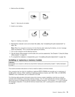
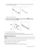
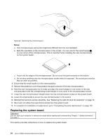
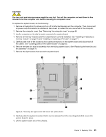
CAUTION: The heat sink and fan assembly might be very hot. Turn off the computer and wait three to five minutes to let the computer cool before removing the computer cover. To replace the heat sink and fan assembly, do the following: 1. Turn off the computer and disconnect all power cords from electrical outlets. 2. Remove the computer cover. See "Removing the computer cover" on page 69. 3. Lay the computer on its side for easier access to the system board. 4. Locate the heat sink and fan assembly. See "Locating parts on the system board" on page 65. 5. Disconnect the heat sink and fan assembly cable from the microprocessor fan connector on the system board. See "Locating parts on the system board" on page 65. 6. Follow this sequence to remove the four screws that secure the heat sink and fan assembly to the system board: a. Partially remove screw 1 , then fully remove screw 2 , and then fully remove screw 1 . b. Partially remove screw 3 , then fully remove screw 4 , and then fully remove screw 3 . Note: Carefully remove the four screws from the system board to avoid any possible damage to the system board. The four screws cannot be removed from the heat sink and fan assembly. Figure 19. Removing the heat sink and fan assembly 7. Lift the failing heat sink and fan assembly off the system board. Notes: a. You might have to gently twist the heat sink and fan assembly to free it from the microprocessor. b. Do not touch the thermal grease while handling the heat sink and fan assembly. 8. Position the new heat sink and fan assembly on the system board so that the four screws are aligned with the holes on the system board. 80 Lenovo M5800 Hardware Maintenance Manual
-
 1
1 -
2
-
3
-
4
-
5
-
6
-
7
-
8
-
9
-
10
-
11
-
12
-
13
-
14
-
15
-
16
-
17
-
18
-
19
-
20
-
21
-
22
-
23
-
24
-
25
-
26
-
27
-
28
-
29
-
30
-
31
-
32
-
33
-
34
-
35
-
36
-
37
-
38
-
39
-
40
-
41
-
42
-
43
-
44
-
45
-
46
-
47
-
48
-
49
-
50
-
51
-
52
-
53
-
54
-
55
-
56
-
57
-
58
-
59
-
60
-
61
-
62
-
63
-
64
-
65
-
66
-
67
-
68
-
69
-
70
-
71
-
72
-
73
-
74
-
75
-
76
-
77
-
78
-
79
-
80
-
 81
81 -
 82
82 -
 83
83 -
 84
84 -
 85
85 -
 86
86 -
 87
87 -
 88
88 -
 89
89 -
 90
90 -
 91
91 -
92
-
93
-
94
-
95
-
96
-
97
-
98
-
99
-
100
-
101
-
102
-
103
-
104
-
105
-
106
-
107
-
108
-
109
-
110
-
111
-
112
-
113
-
114
-
115
-
116
-
117
-
118
-
119
-
120
 |
 |