Lenovo M5800 Lenovo M5800 Hardware Maintenance Manual - Page 96
chassis and push the rubber mounts through the holes.
 |
View all Lenovo M5800 manuals
Add to My Manuals
Save this manual to your list of manuals |
Page 96 highlights
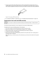
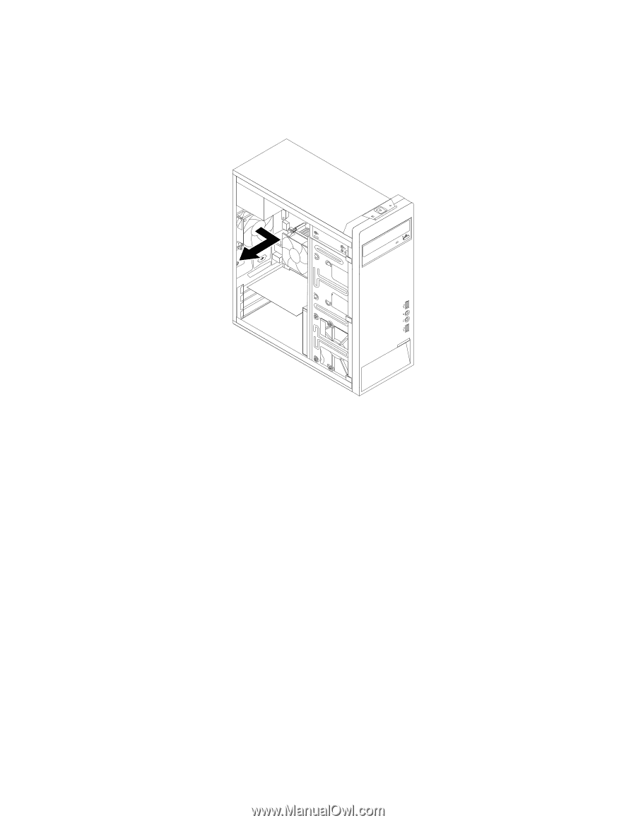
5. The system fan is attached to the chassis by four rubber mounts. Remove the system fan by breaking or cutting the rubber mounts and gently pulling the system fan out of the chassis. Note: The new system fan will have four new rubber mounts attached. Figure 28. Removing the system fan 6. Install the new system fan by aligning the new rubber mounts with the corresponding holes in the chassis and push the rubber mounts through the holes. 90 Lenovo M5800 Hardware Maintenance Manual
-
 1
1 -
2
-
3
-
4
-
5
-
6
-
7
-
8
-
9
-
10
-
11
-
12
-
13
-
14
-
15
-
16
-
17
-
18
-
19
-
20
-
21
-
22
-
23
-
24
-
25
-
26
-
27
-
28
-
29
-
30
-
31
-
32
-
33
-
34
-
35
-
36
-
37
-
38
-
39
-
40
-
41
-
42
-
43
-
44
-
45
-
46
-
47
-
48
-
49
-
50
-
51
-
52
-
53
-
54
-
55
-
56
-
57
-
58
-
59
-
60
-
61
-
62
-
63
-
64
-
65
-
66
-
67
-
68
-
69
-
70
-
71
-
72
-
73
-
74
-
75
-
76
-
77
-
78
-
79
-
80
-
81
-
82
-
83
-
84
-
85
-
86
-
87
-
88
-
89
-
90
-
 91
91 -
 92
92 -
 93
93 -
 94
94 -
 95
95 -
 96
96 -
 97
97 -
 98
98 -
 99
99 -
 100
100 -
 101
101 -
102
-
103
-
104
-
105
-
106
-
107
-
108
-
109
-
110
-
111
-
112
-
113
-
114
-
115
-
116
-
117
-
118
-
119
-
120
 |
 |
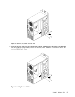
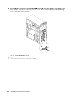
5. The system fan is attached to the chassis by four rubber mounts. Remove the system fan by breaking or
cutting the rubber mounts and gently pulling the system fan out of the chassis.
Note:
The new system fan will have four new rubber mounts attached.
Figure 28. Removing the system fan
6. Install the new system fan by aligning the new rubber mounts with the corresponding holes in the
chassis and push the rubber mounts through the holes.
90
Lenovo M5800 Hardware Maintenance Manual