Lenovo M58p User Guide - Page 40
microprocessor
 |
UPC - 884343322902
View all Lenovo M58p manuals
Add to My Manuals
Save this manual to your list of manuals |
Page 40 highlights
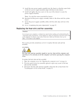
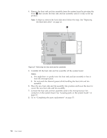
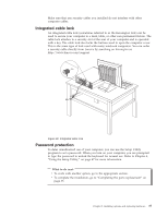
4. Remove the heat sink and fan assembly from the system board by pivoting the lever 1 that secures the heat sink and fan assembly until it is fully in the up position. Note: It helps to remove the hard disk drive before this step. See "Replacing the hard disk drive" on page 22. Figure 27. Removing the heat sink and fan assembly 5. Carefully lift the heat sink and fan assembly off the system board. Notes: a. You might have to gently twist the heat sink and fan assembly to free it from the microprocessor. b. Do not touch the thermal grease while handling the heat sink and fan assembly. 6. Place the new heat sink and fan assembly into position and lower the lever to secure the new heat sink and fan assembly. 7. Connect the heat sink and fan assembly cable to the microprocessor fan connector on the system board. See "Locating parts on the system board" on page 10. 8. Go to "Completing the parts replacement" on page 35. 32 User Guide
-
 1
1 -
2
-
3
-
4
-
5
-
6
-
7
-
8
-
9
-
10
-
11
-
12
-
13
-
14
-
15
-
16
-
17
-
18
-
19
-
20
-
21
-
22
-
23
-
24
-
25
-
26
-
27
-
28
-
29
-
30
-
31
-
32
-
33
-
34
-
 35
35 -
 36
36 -
 37
37 -
 38
38 -
 39
39 -
 40
40 -
 41
41 -
 42
42 -
 43
43 -
 44
44 -
 45
45 -
46
-
47
-
48
-
49
-
50
-
51
-
52
-
53
-
54
-
55
-
56
-
57
-
58
-
59
-
60
-
61
-
62
-
63
-
64
-
65
-
66
-
67
-
68
-
69
-
70
-
71
-
72
-
73
-
74
-
75
-
76
-
77
-
78
-
79
-
80
 |
 |
