Lenovo NetVista Hardware Maintenance Manual (HMM) for Aptiva, IBM PC300, and N - Page 119
Jumper Settings of the System Board of Machine Types 2193 and 2196, and 2196, Jumper/Settings
 |
View all Lenovo NetVista manuals
Add to My Manuals
Save this manual to your list of manuals |
Page 119 highlights
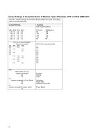
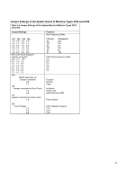
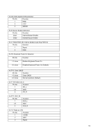
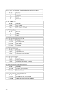
Jumper Settings of the System Board of Machine Types 2193 and 2196 Table 4-4 Jumper Settings of the System Board of Machine Types 2193 and 2196 Jumper/Settings Function Bus Frequency (MHz) JP1 JP2 JP3 JP4 1-2 1-2 1-2 1-2 2-3 1-2 2-3 1-2 2-3 2-3 1-2 2-3 2-3 1-2 1-2 1-2 1-2 1-2 1-2 2-3 1-2 2-3 2-3 2-3 CPU Core Clock Multiplier Jumper connected JP6 JP7 JP8 2-3 1-2 1-2 1-2 1-2 2-3 1-2 2-3 2-3 2-3 2-3 2-3 2-3 1-2 2-3 1-2 1-2 1-2 JP9 CMOS data clear-up Jumper connected 2-3 1-2 J18 Jumper connected to Front Panel 1-2 3-4 J15 Jumper connected to power switch 1-2 CPUCLK 66 100 95 100 66 97 SDRAMCLK 100 133 95 100 66 129 CPU Clock Frequency Ratio 6.0 5.5 5.0 4.5 4.0 3.0 Function Normal Clear Indication Power LED Hard Disk Drive LED Power Button JP5 Vcore Voltage 1-2 3-4 5-6 CPU Voltage Frequency 2.1V 2.2V 2.4V 119
-
 1
1 -
2
-
3
-
4
-
5
-
6
-
7
-
8
-
9
-
10
-
11
-
12
-
13
-
14
-
15
-
16
-
17
-
18
-
19
-
20
-
21
-
22
-
23
-
24
-
25
-
26
-
27
-
28
-
29
-
30
-
31
-
32
-
33
-
34
-
35
-
36
-
37
-
38
-
39
-
40
-
41
-
42
-
43
-
44
-
45
-
46
-
47
-
48
-
49
-
50
-
51
-
52
-
53
-
54
-
55
-
56
-
57
-
58
-
59
-
60
-
61
-
62
-
63
-
64
-
65
-
66
-
67
-
68
-
69
-
70
-
71
-
72
-
73
-
74
-
75
-
76
-
77
-
78
-
79
-
80
-
81
-
82
-
83
-
84
-
85
-
86
-
87
-
88
-
89
-
90
-
91
-
92
-
93
-
94
-
95
-
96
-
97
-
98
-
99
-
100
-
101
-
102
-
103
-
104
-
105
-
106
-
107
-
108
-
109
-
110
-
111
-
112
-
113
-
 114
114 -
 115
115 -
 116
116 -
 117
117 -
 118
118 -
 119
119 -
 120
120 -
 121
121 -
 122
122 -
 123
123 -
 124
124 -
125
-
126
-
127
-
128
-
129
-
130
-
131
-
132
-
133
-
134
-
135
-
136
-
137
-
138
-
139
-
140
-
141
-
142
-
143
-
144
-
145
-
146
-
147
-
148
-
149
-
150
-
151
-
152
-
153
-
154
-
155
-
156
-
157
-
158
-
159
-
160
-
161
-
162
-
163
 |
 |
