Lenovo NetVista Hardware Maintenance Manual (HMM) for Aptiva, IBM PC300, and N - Page 99
Removals and Replacements of machine type 2196
 |
View all Lenovo NetVista manuals
Add to My Manuals
Save this manual to your list of manuals |
Page 99 highlights
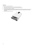
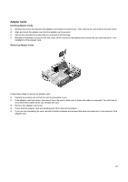
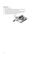
Removals and Replacements of machine type 2196, 2197, and 6344 Before Removing any FRU, Power-OFF The COMPUTER UNPLUG, ALL POWER CORDS FROM ELECTRICAL OUTLETS, THEN DISCONNECT ANY INTERCONNECTING CABLES. ATTENTION: The System board, processors, adapter cards, DIMMs, and upgrade processors can be damaged by electrostatic discharge. Use an electrostatic discharge (ESD) strap to establish personal grounding. If you don't have an ESD strap, establish personal grounding by touching a ground point with one hand before touching the static-sensitive FRUs. The Arrows in the removals and replacements procedures show the direction of movement to remove a field-replaceable unit (FRU), to turn a screw, or the direction to press a tab to release the FRU. Begin all removals by removing the cover (and rear cover, if applicable). When other FURS must be removed prior to removing the failing FRU, they are listed at the top of the page. Go to the removal procedure for each FRU listed. Remove the FRU, and then continue with the removal of failing FRU. To replace a FRU, reverse the removal procedure and follow any notes that PERTAIN to replacement. Before disconnecting any cables, note their location and orientation. Reinstall any new FURS with cabling in their original location. 99
-
 1
1 -
2
-
3
-
4
-
5
-
6
-
7
-
8
-
9
-
10
-
11
-
12
-
13
-
14
-
15
-
16
-
17
-
18
-
19
-
20
-
21
-
22
-
23
-
24
-
25
-
26
-
27
-
28
-
29
-
30
-
31
-
32
-
33
-
34
-
35
-
36
-
37
-
38
-
39
-
40
-
41
-
42
-
43
-
44
-
45
-
46
-
47
-
48
-
49
-
50
-
51
-
52
-
53
-
54
-
55
-
56
-
57
-
58
-
59
-
60
-
61
-
62
-
63
-
64
-
65
-
66
-
67
-
68
-
69
-
70
-
71
-
72
-
73
-
74
-
75
-
76
-
77
-
78
-
79
-
80
-
81
-
82
-
83
-
84
-
85
-
86
-
87
-
88
-
89
-
90
-
91
-
92
-
93
-
 94
94 -
 95
95 -
 96
96 -
 97
97 -
 98
98 -
 99
99 -
 100
100 -
 101
101 -
 102
102 -
 103
103 -
 104
104 -
105
-
106
-
107
-
108
-
109
-
110
-
111
-
112
-
113
-
114
-
115
-
116
-
117
-
118
-
119
-
120
-
121
-
122
-
123
-
124
-
125
-
126
-
127
-
128
-
129
-
130
-
131
-
132
-
133
-
134
-
135
-
136
-
137
-
138
-
139
-
140
-
141
-
142
-
143
-
144
-
145
-
146
-
147
-
148
-
149
-
150
-
151
-
152
-
153
-
154
-
155
-
156
-
157
-
158
-
159
-
160
-
161
-
162
-
163
 |
 |