Lenovo NetVista Hardware Maintenance Manual (HMM) for Aptiva, IBM PC300, and N - Page 56
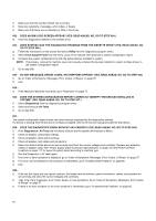
Do Any Messages, Error Codes, Or Symptoms Appear? Yes, Read Ahead. No, Go To Step 005
 |
View all Lenovo NetVista manuals
Add to My Manuals
Save this manual to your list of manuals |
Page 56 highlights
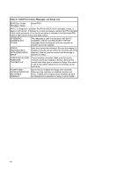
Make sure that the monitor refresh rate is correct. Note any symptoms, messages, error codes, or beeps. Make sure that there are no diskettes or CDs in the drives. 002 - DOES AN IBM LOGO SCREEN APPEAR? (YES, READ AHEAD. NO, GO TO STEP 004.) Insert the diagnostics diskette in the diskette drive. 003 - DOES SYSTEM LOAD THE DIAGNOSTICS PROGRAM FROM THE DISKETTE DRIVE? (YES, READ AHEAD. NO, GO TO STEP 004.) Follow the instructions on the screen and select Utility from the diagnostics program menu. Select Tech Support Form from the menu, press F5 to execute, then generate a system configuration report. Compare the system configuration list with the actual devices installed in system. NOTE: If necessary, remove the machine cover and visually compare the devices installed in system to those shown in the system configuration report. Go to step 006. 004 - DO ANY MESSAGES, ERROR CODES, OR SYMPTOMS APPEAR? (YES, READ AHEAD. NO, GO TO STEP 005) Go to "Index of Symptoms, Messages, Error Codes, or Beeps" on page 57. End. 005 If the keyboard responds incorrectly, go to "Keyboard" on page 75. 006 - DOES THE SYSTEM CONFIGURATION REPORT CORRECTLY IDENTIFY THE DEVICES INSTALLED IN SYSTEM? (YES, READ AHEAD. NO, GO TO STEP 007.) Select Diagnostics from the diagnostics program menu. Select and execute All Tests. Go to step 008. 007 The system configuration report shows only those devices supported by the diagnostics diskette. If a device is missing from the list and is not factory installed, refer to the service manual provided for that device. 008 - DOES THE DIAGNOSTICS FINISH WITHOUT ANY ERRORS? (YES, READ AHEAD. NO, GO TO STEP 009.) If the Diagnostics \ All Tests did not detect a failure but the system still indicates a failure: Check all adapter card jumper settings. Check all adapter cards switch settings. Check all adapter card cables and connectors. Make sure that all of the above are set correctly and show the correct voltages and continuity. Replace any defective cables or adapter cards. See "Power Supply Cable Connector Specifications" on page 127 and Parts/Test Point Locations on page 111 for layout of system board according to machine type Run the Diagnostics \ All Tests again. If an error or other symptom is displayed, go to "Index of Symptoms, Messages, Error Codes, or Beeps" on page 57. If no error can be detected or the symptom is intermittent, go to "Undetermined Problems" on page 80. End 009 If the last test stops and you cannot continue, first make sure all switches, power connectors, cables, and jumpers are set correctly and show the correct voltages and continuity. Take note of any messages, error codes, beeps, or new symptoms. Go to "Index of Symptoms, Messages, Error Codes, or Beeps" on page 57. If there is no error symptom or the error symptom is intermittent, go to "Undetermined Problems" on page 80. 56
-
 1
1 -
2
-
3
-
4
-
5
-
6
-
7
-
8
-
9
-
10
-
11
-
12
-
13
-
14
-
15
-
16
-
17
-
18
-
19
-
20
-
21
-
22
-
23
-
24
-
25
-
26
-
27
-
28
-
29
-
30
-
31
-
32
-
33
-
34
-
35
-
36
-
37
-
38
-
39
-
40
-
41
-
42
-
43
-
44
-
45
-
46
-
47
-
48
-
49
-
50
-
 51
51 -
 52
52 -
 53
53 -
 54
54 -
 55
55 -
 56
56 -
 57
57 -
 58
58 -
 59
59 -
 60
60 -
 61
61 -
62
-
63
-
64
-
65
-
66
-
67
-
68
-
69
-
70
-
71
-
72
-
73
-
74
-
75
-
76
-
77
-
78
-
79
-
80
-
81
-
82
-
83
-
84
-
85
-
86
-
87
-
88
-
89
-
90
-
91
-
92
-
93
-
94
-
95
-
96
-
97
-
98
-
99
-
100
-
101
-
102
-
103
-
104
-
105
-
106
-
107
-
108
-
109
-
110
-
111
-
112
-
113
-
114
-
115
-
116
-
117
-
118
-
119
-
120
-
121
-
122
-
123
-
124
-
125
-
126
-
127
-
128
-
129
-
130
-
131
-
132
-
133
-
134
-
135
-
136
-
137
-
138
-
139
-
140
-
141
-
142
-
143
-
144
-
145
-
146
-
147
-
148
-
149
-
150
-
151
-
152
-
153
-
154
-
155
-
156
-
157
-
158
-
159
-
160
-
161
-
162
-
163
 |
 |