Lenovo NetVista Technical information manual for NetVista 6269, 6568, 6569, 65 - Page 42
MIDI/joystick connector, Internal, connectors, Diskette drive connector
 |
View all Lenovo NetVista manuals
Add to My Manuals
Save this manual to your list of manuals |
Page 42 highlights
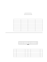
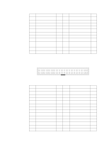
MIDI/joystick connector The external MIDI/joystick connector attaches to the system board through a signal cable that connects to an internal connector on the system board. The following illustration shows the external connector. 15 9 8 1 Table 17. MIDI/Joystick external connector-pin assignments Pin Signal Pin 1 +5 v dc 9 2 JAB1 10 3 JACX 11 4 Ground 12 5 Ground 13 6 JACY 14 7 JAB2 15 8 +5 Signal +5 v dc JBB1 JBCX MIDI out JBCY JBB2 MIDI in Internal connectors The following figures show the connector-pin assignments for various internal connectors on the system board and memory card. Diskette drive connector 2 34 1 33 Table 18. Diskette drive connector-pin assignments Pin 1 2 3 4 5 Signal Ground High density select Ground Not connected Ground I/O I O Pin 18 19 20 21 22 Signal Direction in# Ground Step# Ground Write data# 32 NetVista™ Technical Information Manual I/O O O
-
 1
1 -
2
-
3
-
4
-
5
-
6
-
7
-
8
-
9
-
10
-
11
-
12
-
13
-
14
-
15
-
16
-
17
-
18
-
19
-
20
-
21
-
22
-
23
-
24
-
25
-
26
-
27
-
28
-
29
-
30
-
31
-
32
-
33
-
34
-
35
-
36
-
 37
37 -
 38
38 -
 39
39 -
 40
40 -
 41
41 -
 42
42 -
 43
43 -
 44
44 -
 45
45 -
 46
46 -
 47
47 -
48
-
49
-
50
-
51
-
52
-
53
-
54
-
55
-
56
-
57
-
58
-
59
-
60
-
61
-
62
-
63
-
64
-
65
-
66
-
67
-
68
-
69
-
70
-
71
-
72
 |
 |
