Lenovo PC 300PL Techical Information Manual - Page 22
Recovery jumper, Cable connectors, PC 300PL - tower model
 |
View all Lenovo PC 300PL manuals
Add to My Manuals
Save this manual to your list of manuals |
Page 22 highlights
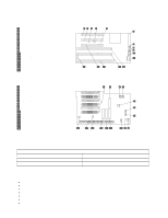
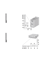
Chapter 2. System board features Some desktop models have a riser card with two PCI slots, one ISA slot, and one shared PCI/ISA slot. The following illustration shows the location of the slot on the PCI/ISA riser card. 1 PCI slot 3 2 PCI slot 2 3 Alert on LAN connector 4 SCSI LED connector 5 Wake on LAN connector 6 FDD connector 7 Fan connector 8 Tamper detector connector 9 Speaker connector 1 RFID connector 11 Power LEDs 12 ISA slot 13 ISA slot 14 System board connector 15 PCI slot 1 16 CD audio connector PC 300PL - tower model The following illustration shows the riser card on the tower model. 1 PCI slots 1-5, lowest to highest 2 Diskette drive connector 3 Hard disk fan 1 connector 4 Hard disk fan 2 connector 5 Front fan connector 6 Wake on LAN connector 7 RFID connector 8 Speaker connector 9 Tamper detector connector 1 SCSI LED connector 11 IDE secondary connector 12 IDE primary connector 13 Power connector 14 Alert on LAN connector 15 212-pin system board connector 16 CD audio connector Recovery jumper The recovery jumper on the system board is used for custom configurations. For the location of the recovery jumper, see the "System board, Types 6584 and 6594" on page 13. Figure 6. Recovery jumper Pins 1 and 2 2 and 3 Description Normal (factory default) Clear CMOS/password, boot block recovery Cable connectors Connections for attaching devices are provided on the back of the computer. The connectors are: USB (2) Mouse Keyboard Serial (2) Parallel Monitor (SVGA or DVI) Audio connectors for line in, line/headphone out, and microphone 14 Technical Information Manual
-
 1
1 -
2
-
3
-
4
-
5
-
6
-
7
-
8
-
9
-
10
-
11
-
12
-
13
-
14
-
15
-
16
-
 17
17 -
 18
18 -
 19
19 -
 20
20 -
 21
21 -
 22
22 -
 23
23 -
 24
24 -
 25
25 -
 26
26 -
 27
27 -
28
-
29
-
30
-
31
-
32
-
33
-
34
-
35
-
36
-
37
-
38
-
39
-
40
-
41
-
42
-
43
-
44
-
45
-
46
-
47
-
48
-
49
-
50
-
51
-
52
-
53
-
54
 |
 |
