Lenovo PC 300PL Techical Information Manual - Page 23
Connector panel, The following illustration shows the connector panel for the tower model
 |
View all Lenovo PC 300PL manuals
Add to My Manuals
Save this manual to your list of manuals |
Page 23 highlights
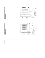
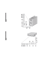
22 11 Chapter 2. System board features Connector panel Each connector for a features that is integrated into the system board can be identified by an icon directly below the connector. A connectors provided by an adapter might not have an identifying icon. For pin-out details on connectors, see Appendix A, "Connector pin assignments" on page 25. The following illustration shows the connector panel for the tower model: 1 USB connector 2 2 Serial connector 2 3 Mouse connector 4 SVGA monitor connector 5 DVI monitor connector 6 Keyboard connector 7 Serial connector 1 8 USB connector 1 9 Parallel connector 1 Microphone connector 11 Line in connector 12 Line/headphone out connector The following illustration shows the connector panel for the desktop model: 1 USB connector 2 2 Serial connector 2 3 SVGA monitor connector 4 DVI monitor connector 5 Mouse connector 6 Keyboard connector 7 Serial connector 1 8 USB connector 1 9 Parallel connector 1 Microphone connector 11 Line in connector 12 Line/headphone out connector 22 1 1 Chapter 2. System board features 15
-
 1
1 -
2
-
3
-
4
-
5
-
6
-
7
-
8
-
9
-
10
-
11
-
12
-
13
-
14
-
15
-
16
-
17
-
 18
18 -
 19
19 -
 20
20 -
 21
21 -
 22
22 -
 23
23 -
 24
24 -
 25
25 -
 26
26 -
 27
27 -
 28
28 -
29
-
30
-
31
-
32
-
33
-
34
-
35
-
36
-
37
-
38
-
39
-
40
-
41
-
42
-
43
-
44
-
45
-
46
-
47
-
48
-
49
-
50
-
51
-
52
-
53
-
54
 |
 |
