Lenovo ThinkCentre E51 User Manual - Page 29
CMOS/Recovery
 |
View all Lenovo ThinkCentre E51 manuals
Add to My Manuals
Save this manual to your list of manuals |
Page 29 highlights
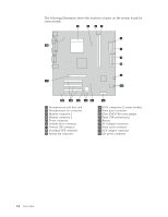
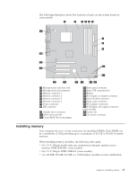
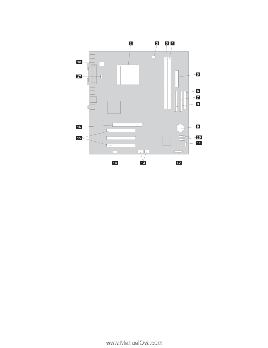
The following illustration shows the locations of parts on the system board for some models. 1 Microprocessor and heat sink 2 Microprocessor fan connector 3 Memory connector 1 4 Memory connector 2 5 Power connector 6 Diskette drive connector 7 Secondary IDE connector 8 Primary IDE connector 9 Battery 10 SATA connectors (2) 11 Clear CMOS/Recovery jumper 12 Power LED connector 13 Front USB connector 14 Front audio connector 15 PCI adapter connectors 16 AGP adapter connector 17 System fan connector 18 12v power connector Chapter 1. Installing options 13
-
 1
1 -
2
-
3
-
4
-
5
-
6
-
7
-
8
-
9
-
10
-
11
-
12
-
13
-
14
-
15
-
16
-
17
-
18
-
19
-
20
-
21
-
22
-
23
-
 24
24 -
 25
25 -
 26
26 -
 27
27 -
 28
28 -
 29
29 -
 30
30 -
 31
31 -
 32
32 -
 33
33 -
 34
34 -
35
-
36
-
37
-
38
-
39
-
40
-
41
-
42
-
43
-
44
-
45
-
46
-
47
-
48
-
49
-
50
-
51
-
52
-
53
-
54
-
55
-
56
-
57
-
58
-
59
-
60
-
61
-
62
-
63
-
64
-
65
-
66
-
67
-
68
 |
 |
The
following
illustration
shows
the
locations
of
parts
on
the
system
board
for
some
models.
±1²
Microprocessor
and
heat
sink
±10²
SATA
connectors
(2)
±2²
Microprocessor
fan
connector
±11²
Clear
CMOS/Recovery
jumper
±3²
Memory
connector
1
±12²
Power
LED
connector
±4²
Memory
connector
2
±13²
Front
USB
connector
±5²
Power
connector
±14²
Front
audio
connector
±6²
Diskette
drive
connector
±15²
PCI
adapter
connectors
±7²
Secondary
IDE
connector
±16²
AGP
adapter
connector
±8²
Primary
IDE
connector
±17²
System
fan
connector
±9²
Battery
±18²
12v
power
connector
Chapter
1.
Installing
options
13