Lenovo ThinkCentre Edge 71 Hardware Maintenance Manual (HMM) (May 2012) - Thin - Page 115
Accessing the system board components and drives
 |
View all Lenovo ThinkCentre Edge 71 manuals
Add to My Manuals
Save this manual to your list of manuals |
Page 115 highlights
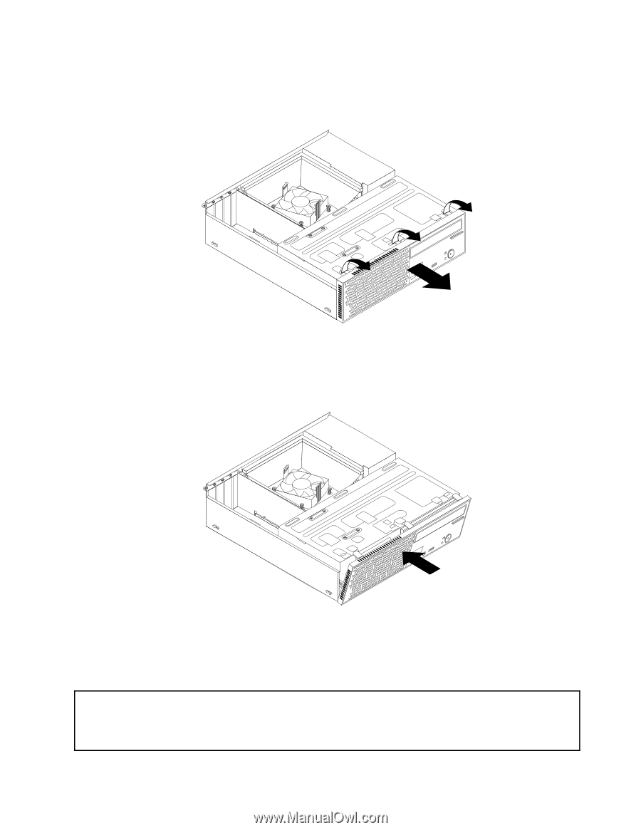
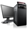
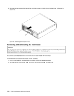
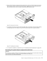
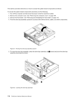
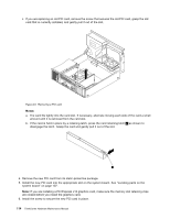
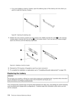
3. Remove the front bezel by releasing the three plastic tabs on the top of the front bezel and pivoting the front bezel outward to remove it from the computer. Carefully lay the front bezel aside without disconnecting the power switch and light-emitting diode (LED) assembly cable. Figure 39. Removing the front bezel 4. To reinstall the front bezel, align the other three plastic tabs on the bottom of the front bezel with the corresponding holes in the chassis, then pivot the front bezel inward until it snaps into position. Figure 40. Reinstalling the front bezel 5. To complete the installation or replacement, go to "Completing the parts replacement" on page 139. Accessing the system board components and drives Attention: Do not open your computer or attempt any repair before reading and understanding the "Important safety information" in the ThinkCentre User Guide. To obtain a copy of the ThinkCentre User Guide, go to: http://www.lenovo.com/ThinkCentreUserGuides Chapter 9. Replacing FRUs (Machine Types: 1578, 1583, and 1652) 111
-
 1
1 -
2
-
3
-
4
-
5
-
6
-
7
-
8
-
9
-
10
-
11
-
12
-
13
-
14
-
15
-
16
-
17
-
18
-
19
-
20
-
21
-
22
-
23
-
24
-
25
-
26
-
27
-
28
-
29
-
30
-
31
-
32
-
33
-
34
-
35
-
36
-
37
-
38
-
39
-
40
-
41
-
42
-
43
-
44
-
45
-
46
-
47
-
48
-
49
-
50
-
51
-
52
-
53
-
54
-
55
-
56
-
57
-
58
-
59
-
60
-
61
-
62
-
63
-
64
-
65
-
66
-
67
-
68
-
69
-
70
-
71
-
72
-
73
-
74
-
75
-
76
-
77
-
78
-
79
-
80
-
81
-
82
-
83
-
84
-
85
-
86
-
87
-
88
-
89
-
90
-
91
-
92
-
93
-
94
-
95
-
96
-
97
-
98
-
99
-
100
-
101
-
102
-
103
-
104
-
105
-
106
-
107
-
108
-
109
-
 110
110 -
 111
111 -
 112
112 -
 113
113 -
 114
114 -
 115
115 -
 116
116 -
 117
117 -
 118
118 -
 119
119 -
 120
120 -
121
-
122
-
123
-
124
-
125
-
126
-
127
-
128
-
129
-
130
-
131
-
132
-
133
-
134
-
135
-
136
-
137
-
138
-
139
-
140
-
141
-
142
-
143
-
144
-
145
-
146
-
147
-
148
-
149
-
150
-
151
-
152
-
153
-
154
-
155
-
156
-
157
-
158
-
159
-
160
-
161
-
162
-
163
-
164
-
165
-
166
-
167
-
168
-
169
-
170
-
171
-
172
-
173
-
174
-
175
-
176
-
177
-
178
-
179
-
180
-
181
-
182
-
183
-
184
-
185
-
186
-
187
-
188
-
189
-
190
-
191
-
192
-
193
-
194
-
195
-
196
-
197
-
198
-
199
-
200
-
201
-
202
-
203
-
204
-
205
-
206
-
207
-
208
-
209
-
210
-
211
-
212
-
213
-
214
-
215
-
216
-
217
-
218
-
219
-
220
-
221
-
222
-
223
-
224
-
225
-
226
-
227
-
228
-
229
-
230
 |
 |