Lenovo ThinkCentre Edge 71 Hardware Maintenance Manual (HMM) (May 2012) - Thin - Page 94
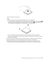
Replacing the heat sink and fan assembly
 |
View all Lenovo ThinkCentre Edge 71 manuals
Add to My Manuals
Save this manual to your list of manuals |
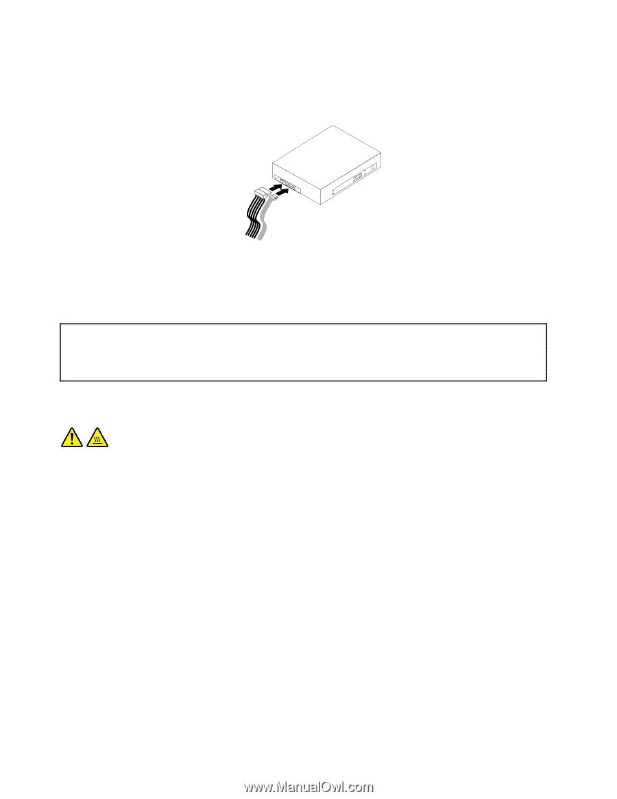
Page 94 highlights
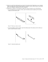
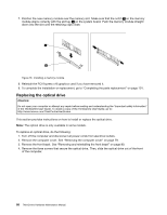
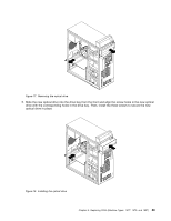
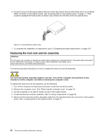
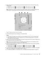
6. Connect one end of the signal cable to the rear of the new optical drive and the other end to an available SATA connector on the system board. See "Locating parts on the system board" on page 77. Then, locate an available five-wire power connector and connect it to the rear of the new optical drive. Figure 19. Connecting the optical drive 7. To complete the installation or replacement, go to "Completing the parts replacement" on page 101. Replacing the heat sink and fan assembly Attention: Do not open your computer or attempt any repair before reading and understanding the "Important safety information" in the ThinkCentre User Guide. To obtain a copy of the ThinkCentre User Guide, go to: http://www.lenovo.com/ThinkCentreUserGuides This section provides instructions on how to replace the heat sink and fan assembly. CAUTION: The heat sink and fan assembly might be very hot. Turn off the computer and wait three to five minutes to let the computer cool before removing the computer cover. To replace the heat sink and fan assembly, do the following: 1. Turn off the computer and disconnect all power cords from electrical outlets. 2. Remove the computer cover. See "Removing the computer cover" on page 79. 3. Lay the computer on its side for easier access to the system board. 4. Locate the heat sink and fan assembly. See "Locating components" on page 76. 5. Disconnect the heat sink and fan assembly cable from the microprocessor fan connector on the system board. See "Locating parts on the system board" on page 77. 90 ThinkCentre Hardware Maintenance Manual
-
 1
1 -
2
-
3
-
4
-
5
-
6
-
7
-
8
-
9
-
10
-
11
-
12
-
13
-
14
-
15
-
16
-
17
-
18
-
19
-
20
-
21
-
22
-
23
-
24
-
25
-
26
-
27
-
28
-
29
-
30
-
31
-
32
-
33
-
34
-
35
-
36
-
37
-
38
-
39
-
40
-
41
-
42
-
43
-
44
-
45
-
46
-
47
-
48
-
49
-
50
-
51
-
52
-
53
-
54
-
55
-
56
-
57
-
58
-
59
-
60
-
61
-
62
-
63
-
64
-
65
-
66
-
67
-
68
-
69
-
70
-
71
-
72
-
73
-
74
-
75
-
76
-
77
-
78
-
79
-
80
-
81
-
82
-
83
-
84
-
85
-
86
-
87
-
88
-
 89
89 -
 90
90 -
 91
91 -
 92
92 -
 93
93 -
 94
94 -
 95
95 -
 96
96 -
 97
97 -
 98
98 -
 99
99 -
100
-
101
-
102
-
103
-
104
-
105
-
106
-
107
-
108
-
109
-
110
-
111
-
112
-
113
-
114
-
115
-
116
-
117
-
118
-
119
-
120
-
121
-
122
-
123
-
124
-
125
-
126
-
127
-
128
-
129
-
130
-
131
-
132
-
133
-
134
-
135
-
136
-
137
-
138
-
139
-
140
-
141
-
142
-
143
-
144
-
145
-
146
-
147
-
148
-
149
-
150
-
151
-
152
-
153
-
154
-
155
-
156
-
157
-
158
-
159
-
160
-
161
-
162
-
163
-
164
-
165
-
166
-
167
-
168
-
169
-
170
-
171
-
172
-
173
-
174
-
175
-
176
-
177
-
178
-
179
-
180
-
181
-
182
-
183
-
184
-
185
-
186
-
187
-
188
-
189
-
190
-
191
-
192
-
193
-
194
-
195
-
196
-
197
-
198
-
199
-
200
-
201
-
202
-
203
-
204
-
205
-
206
-
207
-
208
-
209
-
210
-
211
-
212
-
213
-
214
-
215
-
216
-
217
-
218
-
219
-
220
-
221
-
222
-
223
-
224
-
225
-
226
-
227
-
228
-
229
-
230
 |
 |