Lenovo ThinkCentre Edge 71 Hardware Maintenance Manual (HMM) (May 2012) - Thin - Page 141
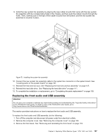
To replace the front audio and USB assembly, do the following
 |
View all Lenovo ThinkCentre Edge 71 manuals
Add to My Manuals
Save this manual to your list of manuals |
Page 141 highlights
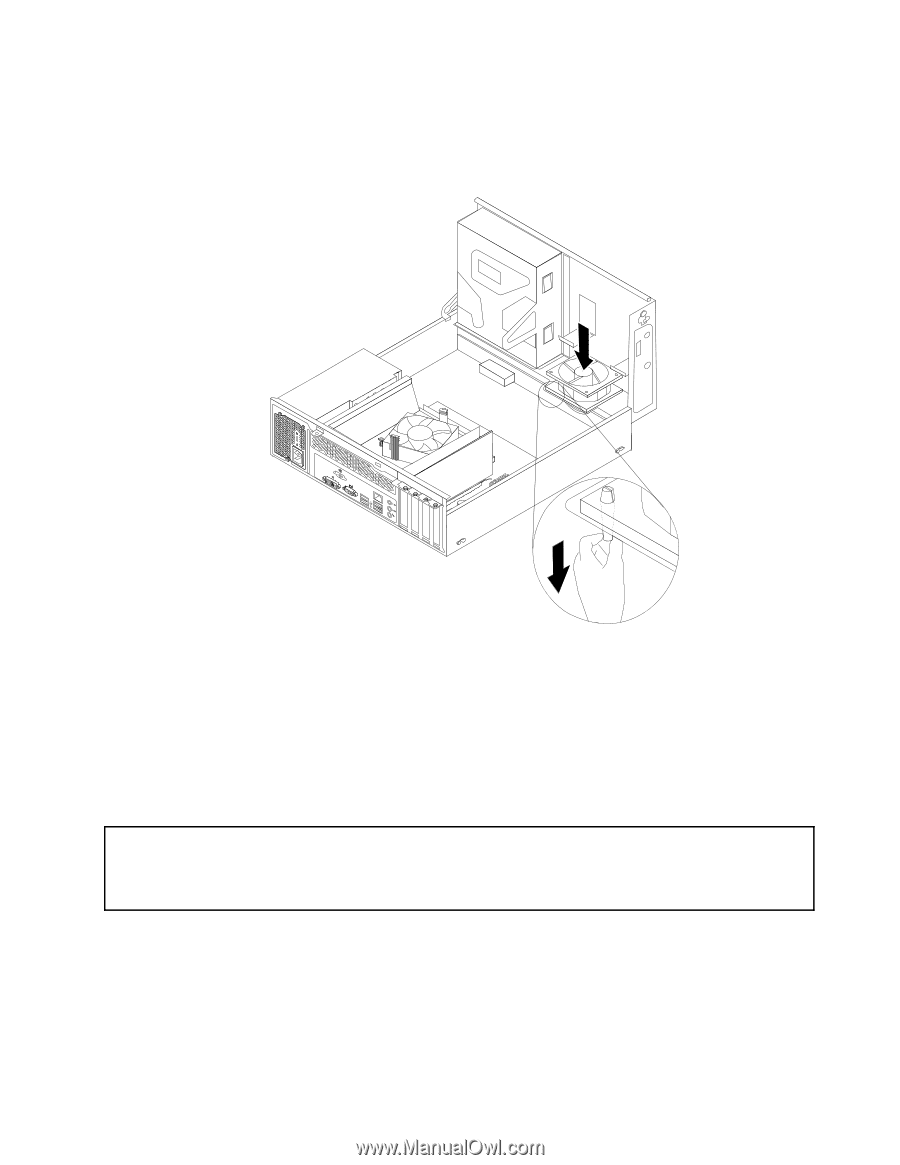
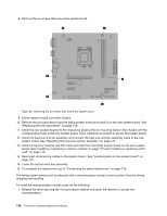
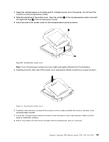
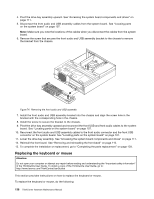
9. Install the new system fan assembly by aligning the new rubber mounts that came with the new system fan assembly with the corresponding holes in the chassis, and then push the rubber mounts through the holes. Then, carefully pull on the tips of the rubber mounts from the bottom until the new system fan assembly is secured in place. Figure 73. Installing the system fan assembly 10. Connect the new system fan assembly cable to the system fan connector on the system board. See "Locating parts on the system board" on page 107. 11. Reinstall the heat sink fan duct. See "Replacing the heat sink and fan assembly" on page 127. 12. Reinstall the hard disk drive. See "Replacing the hard disk drive" on page 117. 13. To complete the installation or replacement, go to "Completing the parts replacement" on page 139. Replacing the front audio and USB assembly Attention: Do not open your computer or attempt any repair before reading and understanding the "Important safety information" in the ThinkCentre User Guide. To obtain a copy of the ThinkCentre User Guide, go to: http://www.lenovo.com/ThinkCentreUserGuides This section provides instructions on how to replace the front audio and USB assembly. To replace the front audio and USB assembly, do the following: 1. Turn off the computer and disconnect all power cords from electrical outlets. 2. Remove the computer cover. See "Removing the computer cover" on page 109. 3. Remove the front bezel. See "Removing and reinstalling the front bezel" on page 110. Chapter 9. Replacing FRUs (Machine Types: 1578, 1583, and 1652) 137
-
 1
1 -
2
-
3
-
4
-
5
-
6
-
7
-
8
-
9
-
10
-
11
-
12
-
13
-
14
-
15
-
16
-
17
-
18
-
19
-
20
-
21
-
22
-
23
-
24
-
25
-
26
-
27
-
28
-
29
-
30
-
31
-
32
-
33
-
34
-
35
-
36
-
37
-
38
-
39
-
40
-
41
-
42
-
43
-
44
-
45
-
46
-
47
-
48
-
49
-
50
-
51
-
52
-
53
-
54
-
55
-
56
-
57
-
58
-
59
-
60
-
61
-
62
-
63
-
64
-
65
-
66
-
67
-
68
-
69
-
70
-
71
-
72
-
73
-
74
-
75
-
76
-
77
-
78
-
79
-
80
-
81
-
82
-
83
-
84
-
85
-
86
-
87
-
88
-
89
-
90
-
91
-
92
-
93
-
94
-
95
-
96
-
97
-
98
-
99
-
100
-
101
-
102
-
103
-
104
-
105
-
106
-
107
-
108
-
109
-
110
-
111
-
112
-
113
-
114
-
115
-
116
-
117
-
118
-
119
-
120
-
121
-
122
-
123
-
124
-
125
-
126
-
127
-
128
-
129
-
130
-
131
-
132
-
133
-
134
-
135
-
 136
136 -
 137
137 -
 138
138 -
 139
139 -
 140
140 -
 141
141 -
 142
142 -
 143
143 -
 144
144 -
 145
145 -
 146
146 -
147
-
148
-
149
-
150
-
151
-
152
-
153
-
154
-
155
-
156
-
157
-
158
-
159
-
160
-
161
-
162
-
163
-
164
-
165
-
166
-
167
-
168
-
169
-
170
-
171
-
172
-
173
-
174
-
175
-
176
-
177
-
178
-
179
-
180
-
181
-
182
-
183
-
184
-
185
-
186
-
187
-
188
-
189
-
190
-
191
-
192
-
193
-
194
-
195
-
196
-
197
-
198
-
199
-
200
-
201
-
202
-
203
-
204
-
205
-
206
-
207
-
208
-
209
-
210
-
211
-
212
-
213
-
214
-
215
-
216
-
217
-
218
-
219
-
220
-
221
-
222
-
223
-
224
-
225
-
226
-
227
-
228
-
229
-
230
 |
 |