Lenovo ThinkCentre Edge 71 Hardware Maintenance Manual (HMM) (May 2012) - Thin - Page 142
Replacing the keyboard or mouse
 |
View all Lenovo ThinkCentre Edge 71 manuals
Add to My Manuals
Save this manual to your list of manuals |
Page 142 highlights
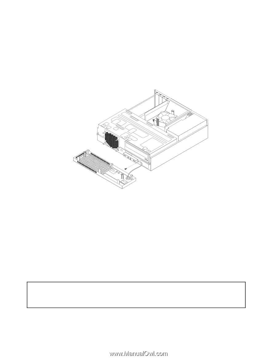
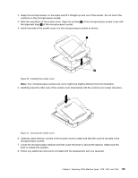
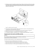
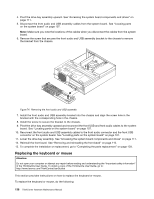
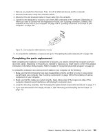
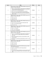
4. Pivot the drive bay assembly upward. See "Accessing the system board components and drives" on page 111. 5. Disconnect the front audio and USB assembly cables from the system board. See "Locating parts on the system board" on page 107. Note: Make sure you note the locations of the cables when you disconnect the cables from the system board. 6. Remove the screw that secures the front audio and USB assembly bracket to the chassis to remove the bracket from the chassis. Figure 74. Removing the front audio and USB assembly 7. Install the front audio and USB assembly bracket into the chassis and align the screw hole in the bracket with the corresponding hole in the chassis. 8. Install the screw to secure the bracket to the chassis. 9. Pivot the drive bay assembly upward and reconnect the front USB and front audio cables to the system board. See "Locating parts on the system board" on page 107. 10. Reconnect the front audio and USB assembly cables to the front audio connector and the front USB connector on the system board. See "Locating parts on the system board" on page 107. 11. Lower the drive bay assembly. See "Accessing the system board components and drives" on page 111. 12. Reinstall the front bezel. See "Removing and reinstalling the front bezel" on page 110. 13. To complete the installation or replacement, go to "Completing the parts replacement" on page 139. Replacing the keyboard or mouse Attention: Do not open your computer or attempt any repair before reading and understanding the "Important safety information" in the ThinkCentre User Guide. To obtain a copy of the ThinkCentre User Guide, go to: http://www.lenovo.com/ThinkCentreUserGuides This section provides instructions on how to replace the keyboard or mouse. To replace the keyboard or mouse, do the following: 138 ThinkCentre Hardware Maintenance Manual
-
 1
1 -
2
-
3
-
4
-
5
-
6
-
7
-
8
-
9
-
10
-
11
-
12
-
13
-
14
-
15
-
16
-
17
-
18
-
19
-
20
-
21
-
22
-
23
-
24
-
25
-
26
-
27
-
28
-
29
-
30
-
31
-
32
-
33
-
34
-
35
-
36
-
37
-
38
-
39
-
40
-
41
-
42
-
43
-
44
-
45
-
46
-
47
-
48
-
49
-
50
-
51
-
52
-
53
-
54
-
55
-
56
-
57
-
58
-
59
-
60
-
61
-
62
-
63
-
64
-
65
-
66
-
67
-
68
-
69
-
70
-
71
-
72
-
73
-
74
-
75
-
76
-
77
-
78
-
79
-
80
-
81
-
82
-
83
-
84
-
85
-
86
-
87
-
88
-
89
-
90
-
91
-
92
-
93
-
94
-
95
-
96
-
97
-
98
-
99
-
100
-
101
-
102
-
103
-
104
-
105
-
106
-
107
-
108
-
109
-
110
-
111
-
112
-
113
-
114
-
115
-
116
-
117
-
118
-
119
-
120
-
121
-
122
-
123
-
124
-
125
-
126
-
127
-
128
-
129
-
130
-
131
-
132
-
133
-
134
-
135
-
136
-
 137
137 -
 138
138 -
 139
139 -
 140
140 -
 141
141 -
 142
142 -
 143
143 -
 144
144 -
 145
145 -
 146
146 -
 147
147 -
148
-
149
-
150
-
151
-
152
-
153
-
154
-
155
-
156
-
157
-
158
-
159
-
160
-
161
-
162
-
163
-
164
-
165
-
166
-
167
-
168
-
169
-
170
-
171
-
172
-
173
-
174
-
175
-
176
-
177
-
178
-
179
-
180
-
181
-
182
-
183
-
184
-
185
-
186
-
187
-
188
-
189
-
190
-
191
-
192
-
193
-
194
-
195
-
196
-
197
-
198
-
199
-
200
-
201
-
202
-
203
-
204
-
205
-
206
-
207
-
208
-
209
-
210
-
211
-
212
-
213
-
214
-
215
-
216
-
217
-
218
-
219
-
220
-
221
-
222
-
223
-
224
-
225
-
226
-
227
-
228
-
229
-
230
 |
 |