Lenovo ThinkCentre M91p Hardware Maintenance Manual - Page 67
Thermal Sensors Test Passed, Voltage Sensors Voltage Regulator
 |
View all Lenovo ThinkCentre M91p manuals
Add to My Manuals
Save this manual to your list of manuals |
Page 67 highlights
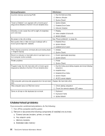
Diagnostic Error Code 170-199-XXX Voltage Sensor(s) test failed, cause unknown 170-250-XXX 170-251-XXX Voltage Sensor(s) Voltage limit error 170-254-XXX Voltage Sensor(s) Voltage Regulator Module error 175-000-XXX Thermal Sensor(s) Test Passed 175-0XX-XXX Thermal Sensor(s) failure 175-195-XXX Thermal Sensor(s) Test aborted by user 175-196-XXX Thermal Sensor(s) test halt, error threshold exceeded 175-197-XXX Thermal Sensor(s) test warning 175-198-XXX Thermal Sensor(s) test aborted 175-199-XXX Thermal Sensor(s) test failed, cause unknown 175-250-XXX 175-251-XXX Thermal Sensor(s) limit error 185-000-XXX Asset Security Test Passed 185-XXX-XXX Asset Security failure 185-278-XXX Asset Security Chassis Intrusion 201-000-XXX System Memory Test Passed FRU/Action 1. See "Undetermined problems" on page 66. 2. Flash the system and re-test. See "Updating (flashing) the BIOS from a disc" on page 186. 3. Replace component under function test. 1. AC/DC power adapter 2. System board 1. Voltage Regulator Module (VRM) 2. Microprocessor 3. System board No action 1. Flash system 2. System board Information only Restart the test, if necessary 1. Press F3 to review the log file. 2. Restart the test to reset the log file. 1. Make sure the component that is called out is connected and/or enabled. See Chapter 6 "Using the Setup Utility program" on page 41. 2. Re-run test. 3. Replace the component that is called out in warning statement. 4. Replace the component under test. 1. If a component is called out, make sure it is connected and/or enabled . 2. Flash the system and re-test. See "Updating (flashing) the BIOS from a disc" on page 186. 3. Go to "Undetermined problems" on page 66. 1. See "Undetermined problems" on page 66. 2. Flash the system and re-test. See "Updating (flashing) the BIOS from a disc" on page 186. 3. Replace component under function test. 1. Check fans 2. Check AC/DC power adapter voltages. 3. Microprocessor 4. System board No action 1. Flash system 2. System board 1. Assure Asset Security Enabled 2. C2 Cover Switch 3. System board No action Chapter 7. Symptom-to-FRU index 61
-
 1
1 -
2
-
3
-
4
-
5
-
6
-
7
-
8
-
9
-
10
-
11
-
12
-
13
-
14
-
15
-
16
-
17
-
18
-
19
-
20
-
21
-
22
-
23
-
24
-
25
-
26
-
27
-
28
-
29
-
30
-
31
-
32
-
33
-
34
-
35
-
36
-
37
-
38
-
39
-
40
-
41
-
42
-
43
-
44
-
45
-
46
-
47
-
48
-
49
-
50
-
51
-
52
-
53
-
54
-
55
-
56
-
57
-
58
-
59
-
60
-
61
-
 62
62 -
 63
63 -
 64
64 -
 65
65 -
 66
66 -
 67
67 -
 68
68 -
 69
69 -
 70
70 -
 71
71 -
 72
72 -
73
-
74
-
75
-
76
-
77
-
78
-
79
-
80
-
81
-
82
-
83
-
84
-
85
-
86
-
87
-
88
-
89
-
90
-
91
-
92
-
93
-
94
-
95
-
96
-
97
-
98
-
99
-
100
-
101
-
102
-
103
-
104
-
105
-
106
-
107
-
108
-
109
-
110
-
111
-
112
-
113
-
114
-
115
-
116
-
117
-
118
-
119
-
120
-
121
-
122
-
123
-
124
-
125
-
126
-
127
-
128
-
129
-
130
-
131
-
132
-
133
-
134
-
135
-
136
-
137
-
138
-
139
-
140
-
141
-
142
-
143
-
144
-
145
-
146
-
147
-
148
-
149
-
150
-
151
-
152
-
153
-
154
-
155
-
156
-
157
-
158
-
159
-
160
-
161
-
162
-
163
-
164
-
165
-
166
-
167
-
168
-
169
-
170
-
171
-
172
-
173
-
174
-
175
-
176
-
177
-
178
-
179
-
180
-
181
-
182
-
183
-
184
-
185
-
186
-
187
-
188
-
189
-
190
-
191
-
192
-
193
-
194
-
195
-
196
-
197
-
198
-
199
-
200
 |
 |
