Lenovo ThinkPad Edge E125 Hardware Maintenance Manual - Page 3

Contents, Status indicators - thinkpad edge e120

Page 3 highlights

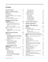
Contents About this manual iii Chapter 1. Safety information 1 General safety 1 Electrical safety 2 Safety inspection guide 3 Handling devices that are sensitive to electrostatic discharge 3 Grounding requirements 4 Safety notices (multilingual translations 4 Chapter 2. Important service information 19 Strategy for replacing FRUs 19 Strategy for replacing a hard disk drive . . . 20 Important notice for replacing a system board 20 How to use error message 20 Strategy for replacing FRUs for CTO, CMV, and GAV 20 Product definition 20 FRU identification for CTO, CMV, and GAV products 21 Chapter 3. General checkout . . . . . 23 What to do first 23 Checkout guide 24 System supporting the Lenovo ThinkVantage Toolbox program and the PC-Doctor for DOS diagnostics program 24 System supporting the Lenovo diagnostics programs 28 Power system checkout 30 Checking the ac power adapter 30 Checking operational charging 31 Checking the battery pack 31 Checking the backup battery 32 Chapter 4. Related service information 33 Restoring the factory contents by using Recovery Disc Set 33 Passwords 34 Power-on password 34 Hard disk password 34 Supervisor password 35 How to remove the power-on password . . . 35 How to remove the hard disk password . . . 35 Power management 36 © Copyright Lenovo 2012 Screen blank mode 36 Sleep (standby) mode 36 Hibernation mode 37 Symptom-to-FRU index 37 Numeric error codes 38 Error messages 39 Beep symptoms 39 No-beep symptoms 39 LCD-related symptoms 40 Intermittent problems 40 Undetermined problems 41 Chapter 5. Status indicators . . . . . 43 Chapter 6. Special keys 45 Chapter 7. FRU replacement notices 47 Screw notices 47 Retaining serial numbers 48 Restoring the serial number of the system unit 48 Retaining the UUID 49 Reading or writing the ECA information . . . 49 Chapter 8. Removing and replacing a FRU 51 Before servicing ThinkPad Edge E120 and E125 models 51 1010 Battery pack 52 1020 Bottom slot cover 53 1030 Memory modules 54 1040 Hard disk drive or solid state drive assembly 54 1050 PCI Express Mini Card for wireless LAN . . 56 1060 PCI Express Mini Card for wireless WAN . . 58 1070 Keyboard 59 1080 Power sub card and microphone . . . . . 61 1090 Top case assembly 62 1100 Bluetooth daughter card 64 1110 Speaker assembly 65 1120 I/O board 65 1130 System board assembly, fan assembly, and backup battery 66 1140 CRT board assembly (with cable) . . . . . 69 1150 DC-in sub card and base cover assembly . . 69 2010 LCD unit 72 2020 LCD bezel assembly 74 i

  • 1
  • 2
  • 3
  • 4
  • 5
  • 6
  • 7
  • 8
  • 9
  • 10
  • 11
  • 12
  • 13
  • 14
  • 15
  • 16
  • 17
  • 18
  • 19
  • 20
  • 21
  • 22
  • 23
  • 24
  • 25
  • 26
  • 27
  • 28
  • 29
  • 30
  • 31
  • 32
  • 33
  • 34
  • 35
  • 36
  • 37
  • 38
  • 39
  • 40
  • 41
  • 42
  • 43
  • 44
  • 45
  • 46
  • 47
  • 48
  • 49
  • 50
  • 51
  • 52
  • 53
  • 54
  • 55
  • 56
  • 57
  • 58
  • 59
  • 60
  • 61
  • 62
  • 63
  • 64
  • 65
  • 66
  • 67
  • 68
  • 69
  • 70
  • 71
  • 72
  • 73
  • 74
  • 75
  • 76
  • 77
  • 78
  • 79
  • 80
  • 81
  • 82
  • 83
  • 84
  • 85
  • 86
  • 87
  • 88
  • 89
  • 90
  • 91
  • 92
  • 93
  • 94
  • 95
  • 96
  • 97
  • 98
  • 99
  • 100
  • 101
  • 102
  • 103
  • 104
  • 105
  • 106

Contents
About this manual
...........
iii
Chapter 1. Safety information
......
1
General safety
.
.
.
.
.
.
.
.
.
.
.
.
.
.
.
.
1
Electrical safety
.
.
.
.
.
.
.
.
.
.
.
.
.
.
.
2
Safety inspection guide
.
.
.
.
.
.
.
.
.
.
.
.
3
Handling devices that are sensitive to electrostatic
discharge
.
.
.
.
.
.
.
.
.
.
.
.
.
.
.
.
.
.
3
Grounding requirements
.
.
.
.
.
.
.
.
.
.
.
.
4
Safety notices (multilingual translations)
.
.
.
.
.
.
4
Chapter 2. Important service
information
..............
19
Strategy for replacing FRUs
.
.
.
.
.
.
.
.
.
19
Strategy for replacing a hard disk drive
.
.
.
20
Important notice for replacing a system
board
.
.
.
.
.
.
.
.
.
.
.
.
.
.
.
.
20
How to use error message
.
.
.
.
.
.
.
.
20
Strategy for replacing FRUs for CTO, CMV, and
GAV
.
.
.
.
.
.
.
.
.
.
.
.
.
.
.
.
.
.
.
20
Product definition
.
.
.
.
.
.
.
.
.
.
.
.
20
FRU identification for CTO, CMV, and GAV
products
.
.
.
.
.
.
.
.
.
.
.
.
.
.
.
21
Chapter 3. General checkout
.....
23
What to do first
.
.
.
.
.
.
.
.
.
.
.
.
.
.
23
Checkout guide
.
.
.
.
.
.
.
.
.
.
.
.
.
.
24
System supporting the Lenovo ThinkVantage
Toolbox program and the PC-Doctor for DOS
diagnostics program
.
.
.
.
.
.
.
.
.
.
24
System supporting the Lenovo diagnostics
programs
.
.
.
.
.
.
.
.
.
.
.
.
.
.
.
28
Power system checkout
.
.
.
.
.
.
.
.
.
.
.
30
Checking the ac power adapter
.
.
.
.
.
.
30
Checking operational charging
.
.
.
.
.
.
31
Checking the battery pack
.
.
.
.
.
.
.
.
31
Checking the backup battery
.
.
.
.
.
.
.
32
Chapter 4. Related service
information
..............
33
Restoring the factory contents by using Recovery
Disc Set
.
.
.
.
.
.
.
.
.
.
.
.
.
.
.
.
.
33
Passwords
.
.
.
.
.
.
.
.
.
.
.
.
.
.
.
.
34
Power-on password
.
.
.
.
.
.
.
.
.
.
.
34
Hard disk password
.
.
.
.
.
.
.
.
.
.
.
34
Supervisor password
.
.
.
.
.
.
.
.
.
.
35
How to remove the power-on password .
.
.
35
How to remove the hard disk password .
.
.
35
Power management
.
.
.
.
.
.
.
.
.
.
.
.
36
Screen blank mode
.
.
.
.
.
.
.
.
.
.
.
36
Sleep (standby) mode
.
.
.
.
.
.
.
.
.
.
36
Hibernation mode
.
.
.
.
.
.
.
.
.
.
.
37
Symptom-to-FRU index
.
.
.
.
.
.
.
.
.
.
.
37
Numeric error codes
.
.
.
.
.
.
.
.
.
.
38
Error messages
.
.
.
.
.
.
.
.
.
.
.
.
39
Beep symptoms
.
.
.
.
.
.
.
.
.
.
.
.
39
No-beep symptoms
.
.
.
.
.
.
.
.
.
.
.
39
LCD-related symptoms
.
.
.
.
.
.
.
.
.
40
Intermittent problems
.
.
.
.
.
.
.
.
.
.
40
Undetermined problems
.
.
.
.
.
.
.
.
.
41
Chapter 5. Status indicators
.....
43
Chapter 6. Special keys
........
45
Chapter 7. FRU replacement
notices
................
47
Screw notices
.
.
.
.
.
.
.
.
.
.
.
.
.
.
.
47
Retaining serial numbers
.
.
.
.
.
.
.
.
.
.
.
48
Restoring the serial number of the system
unit
.
.
.
.
.
.
.
.
.
.
.
.
.
.
.
.
.
48
Retaining the UUID
.
.
.
.
.
.
.
.
.
.
.
49
Reading or writing the ECA information .
.
.
49
Chapter 8. Removing and replacing a
FRU
..................
51
Before servicing ThinkPad Edge E120 and E125
models
.
.
.
.
.
.
.
.
.
.
.
.
.
.
.
.
.
.
51
1010 Battery pack
.
.
.
.
.
.
.
.
.
.
.
.
.
52
1020 Bottom slot cover
.
.
.
.
.
.
.
.
.
.
.
53
1030 Memory modules
.
.
.
.
.
.
.
.
.
.
.
54
1040 Hard disk drive or solid state drive
assembly
.
.
.
.
.
.
.
.
.
.
.
.
.
.
.
.
.
54
1050 PCI Express Mini Card for wireless LAN
.
.
56
1060 PCI Express Mini Card for wireless WAN .
.
58
1070 Keyboard
.
.
.
.
.
.
.
.
.
.
.
.
.
.
59
1080 Power sub card and microphone
.
.
.
.
.
61
1090 Top case assembly
.
.
.
.
.
.
.
.
.
.
.
62
1100 Bluetooth daughter card
.
.
.
.
.
.
.
.
64
1110 Speaker assembly
.
.
.
.
.
.
.
.
.
.
.
65
1120 I/O board
.
.
.
.
.
.
.
.
.
.
.
.
.
.
65
1130 System board assembly, fan assembly, and
backup battery
.
.
.
.
.
.
.
.
.
.
.
.
.
.
66
1140 CRT board assembly (with cable)
.
.
.
.
.
69
1150 DC-in sub card and base cover assembly .
.
69
2010 LCD unit
.
.
.
.
.
.
.
.
.
.
.
.
.
.
.
72
2020 LCD bezel assembly
.
.
.
.
.
.
.
.
.
.
74
© Copyright Lenovo 2012
i