Lenovo ThinkPad Edge E125 Hardware Maintenance Manual - Page 72
System board assembly, fan assembly, and backup battery
 |
View all Lenovo ThinkPad Edge E125 manuals
Add to My Manuals
Save this manual to your list of manuals |
Page 72 highlights
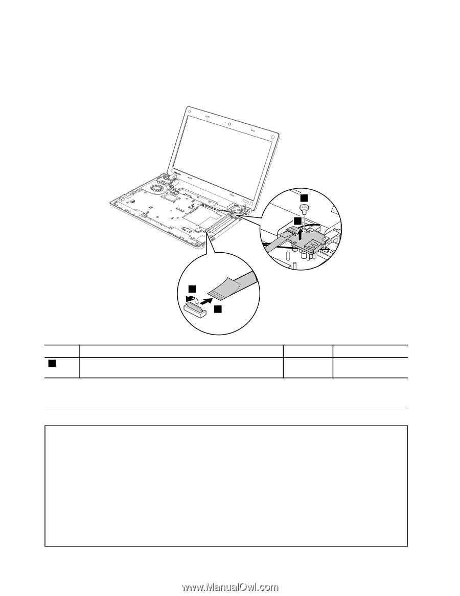
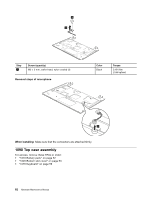
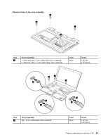
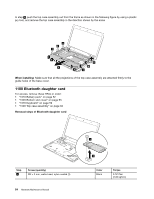
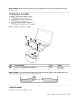
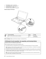
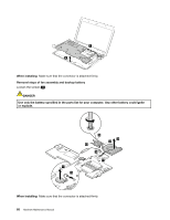
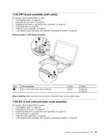
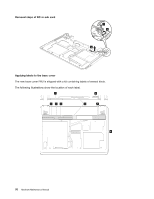
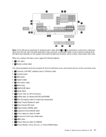
• "1010 Battery pack" on page 52 • "1020 Bottom slot cover" on page 53 • "1070 Keyboard" on page 59 • "1090 Top case assembly" on page 62 Removal steps of I/O board 3 4 1 2 Step 3 Screw (quantity) M2 × 3 mm, wafer-head, nylon-coated (1) Color Black Torque 0.181 Nm (1.85 kgfcm) When installing: Make sure that the connector is attached firmly. 1130 System board assembly, fan assembly, and backup battery Important notices for handling the system board: When handling the system board, bear the following in mind. • The system board has an accelerometer, which can be broken if several thousands of G-forces are applied. Note: Dropping a system board from a height of as little as 6 inches so that it falls flat on a hard bench can subject the accelerometer to as much as 6,000 G's of shock. • Be careful not to drop the system board on a bench top that has a hard surface, such as metal, wood, or composite. • If a system board is dropped, test it using PC-Doctor for DOS if your system supports PC-Doctor for DOS, to make sure that the HDD Active Protection System™ still functions. Note: If the test shows that the HDD Active Protection System is not functioning, be sure to document the drop in any reject report, and replace the system board. 66 Hardware Maintenance Manual
-
 1
1 -
2
-
3
-
4
-
5
-
6
-
7
-
8
-
9
-
10
-
11
-
12
-
13
-
14
-
15
-
16
-
17
-
18
-
19
-
20
-
21
-
22
-
23
-
24
-
25
-
26
-
27
-
28
-
29
-
30
-
31
-
32
-
33
-
34
-
35
-
36
-
37
-
38
-
39
-
40
-
41
-
42
-
43
-
44
-
45
-
46
-
47
-
48
-
49
-
50
-
51
-
52
-
53
-
54
-
55
-
56
-
57
-
58
-
59
-
60
-
61
-
62
-
63
-
64
-
65
-
66
-
 67
67 -
 68
68 -
 69
69 -
 70
70 -
 71
71 -
 72
72 -
 73
73 -
 74
74 -
 75
75 -
 76
76 -
 77
77 -
78
-
79
-
80
-
81
-
82
-
83
-
84
-
85
-
86
-
87
-
88
-
89
-
90
-
91
-
92
-
93
-
94
-
95
-
96
-
97
-
98
-
99
-
100
-
101
-
102
-
103
-
104
-
105
-
106
 |
 |