Lenovo ThinkPad W520 Hardware Maintenance Manual - Page 108
Removal steps of system board and magnesium structure frame, When installing, Removal steps of MDC
 |
View all Lenovo ThinkPad W520 manuals
Add to My Manuals
Save this manual to your list of manuals |
Page 108 highlights
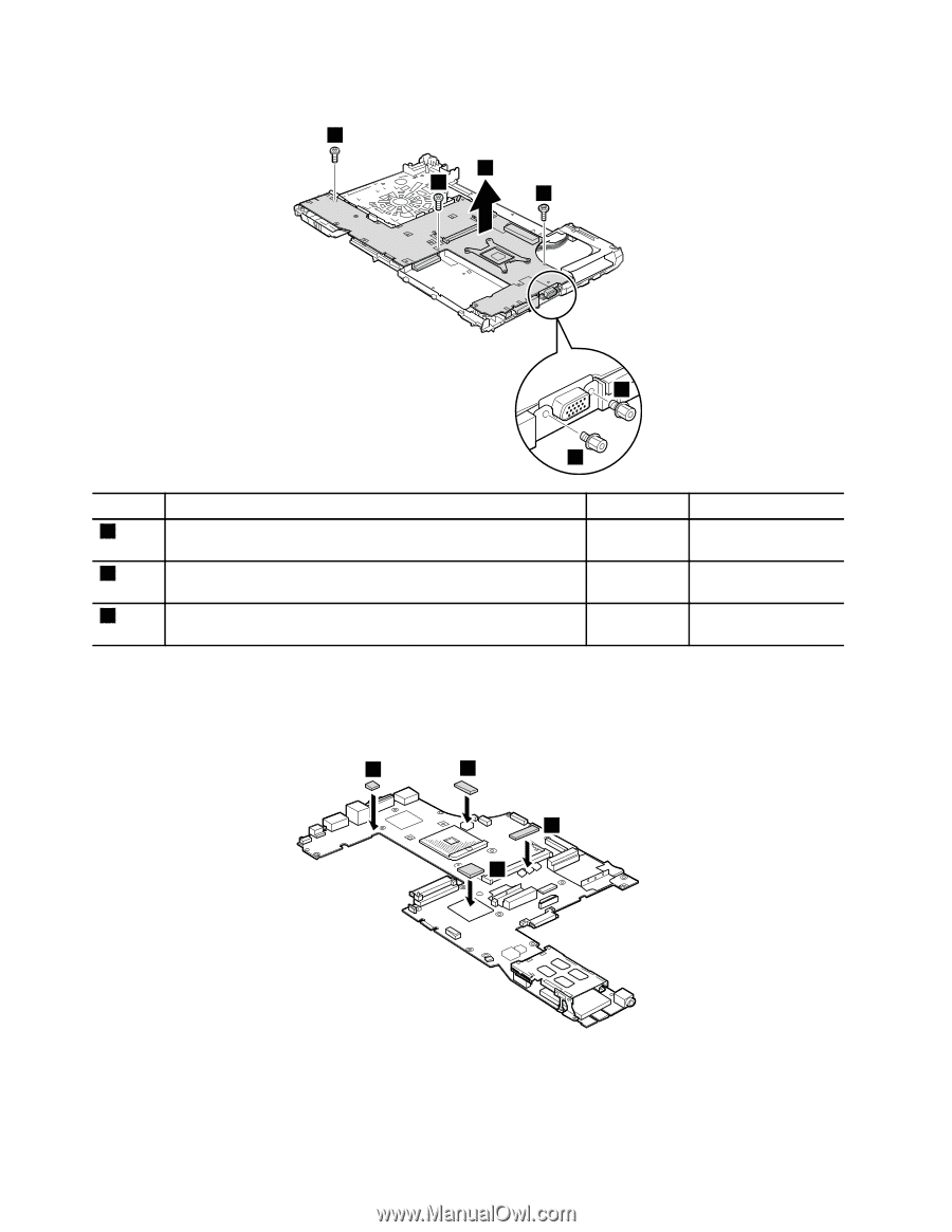
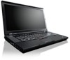
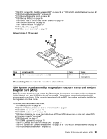
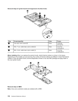
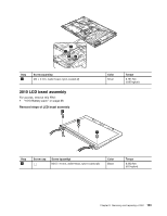
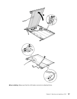
Removal steps of system board and magnesium structure frame 2 4 2 3 1 1 Step 1 2 3 Screw (quantity) Hex stud, nylon-coated (2) M2 × 7 mm, wafer-head, nylon-coated (2) M2 × 3 mm, wafer-head, nylon-coated (1) Color Silver Silver Silver Torque 0.392 Nm (4.0 kgfcm) 0.181 Nm (1.85 kgfcm) 0.181 Nm (1.85 kgfcm) When installing When you replace the system board, attach thermal rubbers as shown in this figure. Depending on the models you are servicing, the number of thermal rubbers are different. Check the thermal rubbers on the old system board, and find duplicates of them in the new FRU package and apply them to the new system board. a b c d Removal steps of MDC Note: Only some selected models are installed with a MDC. 102 Hardware Maintenance Manual
-
 1
1 -
2
-
3
-
4
-
5
-
6
-
7
-
8
-
9
-
10
-
11
-
12
-
13
-
14
-
15
-
16
-
17
-
18
-
19
-
20
-
21
-
22
-
23
-
24
-
25
-
26
-
27
-
28
-
29
-
30
-
31
-
32
-
33
-
34
-
35
-
36
-
37
-
38
-
39
-
40
-
41
-
42
-
43
-
44
-
45
-
46
-
47
-
48
-
49
-
50
-
51
-
52
-
53
-
54
-
55
-
56
-
57
-
58
-
59
-
60
-
61
-
62
-
63
-
64
-
65
-
66
-
67
-
68
-
69
-
70
-
71
-
72
-
73
-
74
-
75
-
76
-
77
-
78
-
79
-
80
-
81
-
82
-
83
-
84
-
85
-
86
-
87
-
88
-
89
-
90
-
91
-
92
-
93
-
94
-
95
-
96
-
97
-
98
-
99
-
100
-
101
-
102
-
 103
103 -
 104
104 -
 105
105 -
 106
106 -
 107
107 -
 108
108 -
 109
109 -
 110
110 -
 111
111 -
 112
112 -
 113
113 -
114
-
115
-
116
-
117
-
118
-
119
-
120
-
121
-
122
-
123
-
124
-
125
-
126
-
127
-
128
-
129
-
130
-
131
-
132
-
133
-
134
-
135
-
136
-
137
-
138
-
139
-
140
-
141
-
142
-
143
-
144
-
145
-
146
-
147
-
148
-
149
-
150
-
151
-
152
-
153
-
154
-
155
-
156
-
157
-
158
-
159
-
160
-
161
-
162
-
163
-
164
-
165
-
166
-
167
-
168
-
169
-
170
-
171
-
172
 |
 |