Lenovo ThinkPad W520 Hardware Maintenance Manual - Page 96
Loosen the screws
 |
View all Lenovo ThinkPad W520 manuals
Add to My Manuals
Save this manual to your list of manuals |
Page 96 highlights
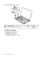
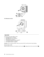
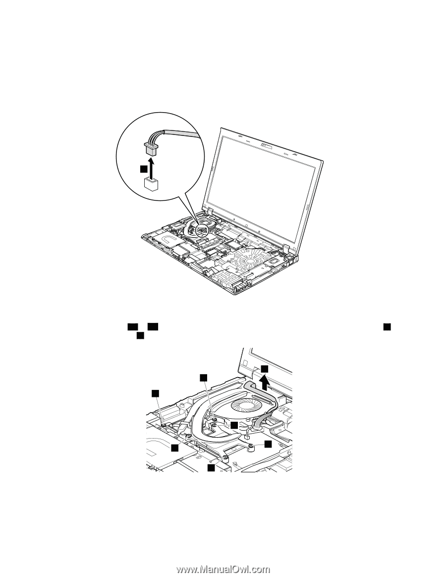
• "1010 Battery pack" on page 66 • "1030 DIMM slot cover" on page 68 • "1060 Keyboard" on page 72 • "1100 Keyboard bezel assembly" on page 82 • "1140 Speaker assembly" on page 88 Removal steps of thermal module 1 When installing: Make sure that the connectors are attached firmly. Note: Loosen the screws 3a to 3d in order, but do not remove them. Some models do not have screws 4 . For those models, skip step 4 . 2 4 4 3a 3c 3d 3b 90 Hardware Maintenance Manual
-
 1
1 -
2
-
3
-
4
-
5
-
6
-
7
-
8
-
9
-
10
-
11
-
12
-
13
-
14
-
15
-
16
-
17
-
18
-
19
-
20
-
21
-
22
-
23
-
24
-
25
-
26
-
27
-
28
-
29
-
30
-
31
-
32
-
33
-
34
-
35
-
36
-
37
-
38
-
39
-
40
-
41
-
42
-
43
-
44
-
45
-
46
-
47
-
48
-
49
-
50
-
51
-
52
-
53
-
54
-
55
-
56
-
57
-
58
-
59
-
60
-
61
-
62
-
63
-
64
-
65
-
66
-
67
-
68
-
69
-
70
-
71
-
72
-
73
-
74
-
75
-
76
-
77
-
78
-
79
-
80
-
81
-
82
-
83
-
84
-
85
-
86
-
87
-
88
-
89
-
90
-
 91
91 -
 92
92 -
 93
93 -
 94
94 -
 95
95 -
 96
96 -
 97
97 -
 98
98 -
 99
99 -
 100
100 -
 101
101 -
102
-
103
-
104
-
105
-
106
-
107
-
108
-
109
-
110
-
111
-
112
-
113
-
114
-
115
-
116
-
117
-
118
-
119
-
120
-
121
-
122
-
123
-
124
-
125
-
126
-
127
-
128
-
129
-
130
-
131
-
132
-
133
-
134
-
135
-
136
-
137
-
138
-
139
-
140
-
141
-
142
-
143
-
144
-
145
-
146
-
147
-
148
-
149
-
150
-
151
-
152
-
153
-
154
-
155
-
156
-
157
-
158
-
159
-
160
-
161
-
162
-
163
-
164
-
165
-
166
-
167
-
168
-
169
-
170
-
171
-
172
 |
 |
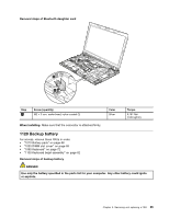
•
“1010 Battery pack” on page 66
•
“1030 DIMM slot cover” on page 68
•
“1060 Keyboard” on page 72
•
“1100 Keyboard bezel assembly” on page 82
•
“1140 Speaker assembly” on page 88
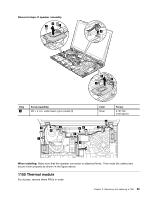
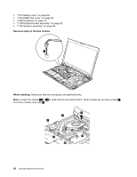
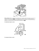
Removal steps of thermal module
1
When installing:
Make sure that the connectors are attached firmly.
Note:
Loosen the screws
3a
to
3d
in order, but do not remove them. Some models do not have screws
4
.
For those models, skip step
4
.
2
3b
3a
3c
3d
4
4
90
Hardware Maintenance Manual