Lenovo ThinkPad W520 Hardware Maintenance Manual - Page 112
Removal steps of LCD cable, camera cable, LCD panel, and hinges, When installing, the panel.
 |
View all Lenovo ThinkPad W520 manuals
Add to My Manuals
Save this manual to your list of manuals |
Page 112 highlights
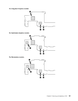
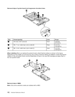
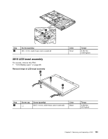
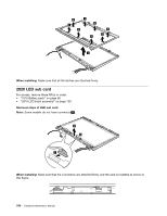
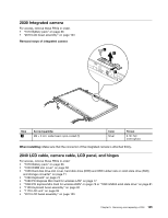
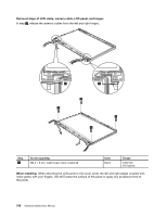
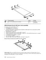
Removal steps of LCD cable, camera cable, LCD panel, and hinges In step 1 , release the antenna cables from the left and right hinges. 1 1 2 2 2 2 Step 2 Screw (quantity) M2.5 × 6 mm, wafer-head, nylon-coated (4) Color Black Torque 0.392 Nm (4.0 kgfcm) When installing: When attaching the LCD panel to the cover, press the left and right edges covered with metal gently with your fingers. DO NOT press the surface of the panel or apply any excessive force to the panel. 106 Hardware Maintenance Manual
-
 1
1 -
2
-
3
-
4
-
5
-
6
-
7
-
8
-
9
-
10
-
11
-
12
-
13
-
14
-
15
-
16
-
17
-
18
-
19
-
20
-
21
-
22
-
23
-
24
-
25
-
26
-
27
-
28
-
29
-
30
-
31
-
32
-
33
-
34
-
35
-
36
-
37
-
38
-
39
-
40
-
41
-
42
-
43
-
44
-
45
-
46
-
47
-
48
-
49
-
50
-
51
-
52
-
53
-
54
-
55
-
56
-
57
-
58
-
59
-
60
-
61
-
62
-
63
-
64
-
65
-
66
-
67
-
68
-
69
-
70
-
71
-
72
-
73
-
74
-
75
-
76
-
77
-
78
-
79
-
80
-
81
-
82
-
83
-
84
-
85
-
86
-
87
-
88
-
89
-
90
-
91
-
92
-
93
-
94
-
95
-
96
-
97
-
98
-
99
-
100
-
101
-
102
-
103
-
104
-
105
-
106
-
 107
107 -
 108
108 -
 109
109 -
 110
110 -
 111
111 -
 112
112 -
 113
113 -
 114
114 -
 115
115 -
 116
116 -
 117
117 -
118
-
119
-
120
-
121
-
122
-
123
-
124
-
125
-
126
-
127
-
128
-
129
-
130
-
131
-
132
-
133
-
134
-
135
-
136
-
137
-
138
-
139
-
140
-
141
-
142
-
143
-
144
-
145
-
146
-
147
-
148
-
149
-
150
-
151
-
152
-
153
-
154
-
155
-
156
-
157
-
158
-
159
-
160
-
161
-
162
-
163
-
164
-
165
-
166
-
167
-
168
-
169
-
170
-
171
-
172
 |
 |
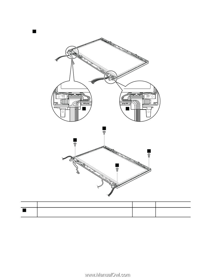
Removal steps of LCD cable, camera cable, LCD panel, and hinges
In step
1
, release the antenna cables from the left and right hinges.
1
1
2
2
2
2
Step
Screw (quantity)
Color
Torque
2
M2.5 × 6 mm, wafer-head, nylon-coated (4)
Black
0.392 Nm
(4.0 kgfcm)
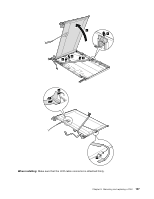
When installing:
When attaching the LCD panel to the cover, press the left and right edges covered with
metal gently with your fingers. DO NOT press the surface of the panel or apply any excessive force to
the panel.
106
Hardware Maintenance Manual