Lenovo ThinkServer RD330 (English) Installation and User Guide - Page 29
Front panel, 5-inch hard disk drive area, Slim optical drive
 |
View all Lenovo ThinkServer RD330 manuals
Add to My Manuals
Save this manual to your list of manuals |
Page 29 highlights
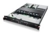
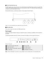
5 2.5-inch hard disk drive area The EMI integrity and cooling of the server are protected by having all drive bays covered or occupied. The number of the installed hard disk drives in your server varies by model. The vacant hard disk drive bays are occupied by dummy hard disk drive trays. The hard disk drive bay numbers are marked on the top edge of the front bezel. 0 2 4 1 3 5 0 2 4 1 3 5 Figure 7. 2.5-inch hard disk drive bay numbers (top view of the server) 6 Slim optical drive Some server models come with a slim SATA optical drive. Front panel This topic provides information to help you locate the controls, connectors, and LEDs on the front panel of the server. The following illustration shows the controls, connectors, and LEDs on the front panel of the server. ID Figure 8. Front panel 1 Power switch with power status LED 2 ID button with ID LED 3 Network Interface Controller (NIC) 1 status LED 4 NIC 2 status LED 5 System error LED 6 Front USB connector 1 7 Front USB connector 2 8 Front VGA DB-15 connector Note: The front VGA DB-15 connector is only available in server models with 2.5-inch hard disk drives. Chapter 3. Product overview 17
-
 1
1 -
2
-
3
-
4
-
5
-
6
-
7
-
8
-
9
-
10
-
11
-
12
-
13
-
14
-
15
-
16
-
17
-
18
-
19
-
20
-
21
-
22
-
23
-
 24
24 -
 25
25 -
 26
26 -
 27
27 -
 28
28 -
 29
29 -
 30
30 -
 31
31 -
 32
32 -
 33
33 -
 34
34 -
35
-
36
-
37
-
38
-
39
-
40
-
41
-
42
-
43
-
44
-
45
-
46
-
47
-
48
-
49
-
50
-
51
-
52
-
53
-
54
-
55
-
56
-
57
-
58
-
59
-
60
-
61
-
62
-
63
-
64
-
65
-
66
-
67
-
68
-
69
-
70
-
71
-
72
-
73
-
74
-
75
-
76
-
77
-
78
-
79
-
80
-
81
-
82
-
83
-
84
-
85
-
86
-
87
-
88
-
89
-
90
-
91
-
92
-
93
-
94
-
95
-
96
-
97
-
98
-
99
-
100
-
101
-
102
-
103
-
104
-
105
-
106
-
107
-
108
-
109
-
110
-
111
-
112
-
113
-
114
-
115
-
116
-
117
-
118
-
119
-
120
-
121
-
122
-
123
-
124
-
125
-
126
-
127
-
128
-
129
-
130
-
131
-
132
-
133
-
134
-
135
-
136
-
137
-
138
-
139
-
140
-
141
-
142
-
143
-
144
-
145
-
146
-
147
-
148
-
149
-
150
-
151
-
152
-
153
-
154
-
155
-
156
-
157
-
158
-
159
-
160
-
161
-
162
-
163
-
164
-
165
-
166
-
167
-
168
-
169
-
170
-
171
-
172
-
173
-
174
-
175
-
176
-
177
-
178
-
179
-
180
-
181
-
182
-
183
-
184
-
185
-
186
-
187
-
188
-
189
-
190
-
191
-
192
 |
 |
