Lexmark X782e IPDS Emulation User’s Guide - Page 54
Mainframe Offset Stacking, Option Card Menu > IPDS MENU > MAP OUTPUT BIN, Mapping 1
 |
View all Lexmark X782e manuals
Add to My Manuals
Save this manual to your list of manuals |
Page 54 highlights
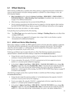
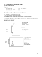
finisher bin 2, which supports offset stacking. See MAP OUTPUT BINS Menu Options on page 40 for details on bin mapping. 5.1.2 Mainframe Offset Stacking For MVS JES2/JES3 offset stacking is controlled by the COPYMARK parameter contained in the printer device definition statement in the JES2/JES3 initialization member. The following examples illustrate the options and syntax for both JES2/JES3. Example 1- JES2 JES2 Specifications using the COPYMARK parameter. (See note): COPYMARK=DATASET COPYMARK=JOB COPYMARK=CONSTANT Offset stacking increment on dataset boundary. Offset stacking increment on job boundary. No offset stacking is performed. Example 2 - JES3 JES3 Specifications using the COPYMARK parameter. (See note): COPYMARK=C COPYMARK=J COPYMARK=N Offset stacking increment on dataset boundary. Offset stacking increment on job boundary. No offset stacking is performed. Note: Copy marks are not generated by the IPDS emulation. Example 3 - Output bin selection The host default output bin selection number is 1, which selects the printer standard bin. If offset stacking is supported in the printer standard bin, offset stacking will be performed. Following are different ways to ensure jobs are offset. The following examples assume that an optional finisher is installed and offset stacking is supported in the finisher physical bin 1. • Specify OUTBIN in the JCL statements as follows: //OUT1 OUTPUT OUTBIN=2 //DDNAME DD SYSOUT=CLASS,OUTPUT=(*,OUT1) • Specify OUTBIN=2 in the OUTPUT DD card of your IEBGENER job. • In the printer's Option Card Menu > IPDS MENU > MAP OUTPUT BIN menu, change Bin Mapping 1 output bin value from Standard Bin to Bin 1. (Assumes the host output bin selection number is 1.) This routes all jobs that would normally have gone to the printer standard bin to finisher bin 1, which supports offset stacking. See MAP OUTPUT BINS Menu Options on page 40 for details on bin mapping. The following examples assume that an optional finisher is installed and offset stacking is supported in the finisher physical bin 2. • Specify OUTBIN in the JCL statements as follows: //OUT1 OUTPUT OUTBIN=3 //DDNAME DD SYSOUT=CLASS,OUTPUT=(*,OUT1) • Specify OUTBIN=3 in the OUTPUT DD card of your IEBGENER job. • In the printer's Option Card Menu > IPDS MENU > MAP OUTPUT BIN menu, change Bin Mapping 1 output bin value from Standard Bin to Bin 2. (Assumes the host output bin selection 54
-
 1
1 -
2
-
3
-
4
-
5
-
6
-
7
-
8
-
9
-
10
-
11
-
12
-
13
-
14
-
15
-
16
-
17
-
18
-
19
-
20
-
21
-
22
-
23
-
24
-
25
-
26
-
27
-
28
-
29
-
30
-
31
-
32
-
33
-
34
-
35
-
36
-
37
-
38
-
39
-
40
-
41
-
42
-
43
-
44
-
45
-
46
-
47
-
48
-
 49
49 -
 50
50 -
 51
51 -
 52
52 -
 53
53 -
 54
54 -
 55
55 -
 56
56 -
 57
57 -
 58
58 -
 59
59 -
60
-
61
-
62
-
63
-
64
-
65
-
66
-
67
-
68
-
69
-
70
-
71
-
72
-
73
-
74
-
75
-
76
-
77
-
78
-
79
-
80
-
81
-
82
-
83
-
84
-
85
-
86
-
87
-
88
-
89
-
90
-
91
-
92
-
93
-
94
-
95
-
96
-
97
-
98
-
99
-
100
-
101
-
102
-
103
-
104
-
105
-
106
-
107
-
108
-
109
-
110
-
111
-
112
-
113
-
114
-
115
-
116
-
117
-
118
-
119
-
120
-
121
-
122
-
123
-
124
-
125
-
126
-
127
-
128
-
129
 |
 |
